Cisco SD-WAN: Basic Configuration Lab
This post walks you through how to get a Cisco SD-WAN lab operational with a minimal number of steps. Sometimes the most difficult part of learning a new technology is reaching the point of basic operation where you can then really begin to explore how things work and compare it to what you already know. Some background information, tips and caveats are also briefly explored, but the intention is to get you forwarding user traffic with minimum hassle while learning about the fundamental architecture of the Cisco SD-WAN solution.
This post is also available on LinkedIn and Medium.
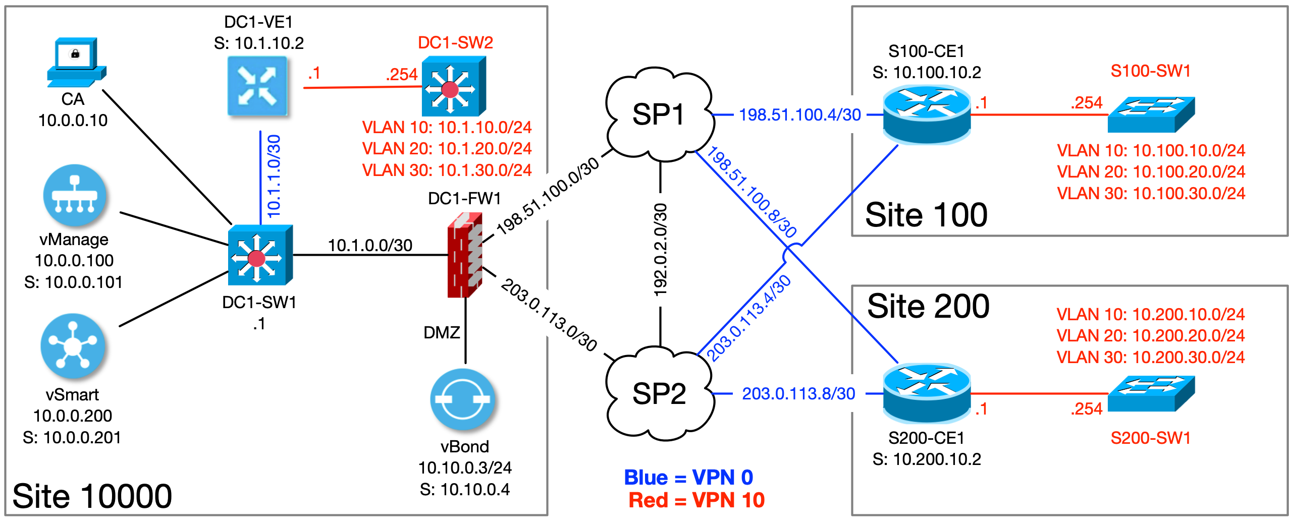
This is the topology we’ll be using for this lab:
There are a few excellent resources available on how to stand up the controller infrastructure. I highly recommend reading these posts by Alin Iorguta and Brad Searle. My friend Tim McConnaughy also has an incredible series of posts on understanding Cisco’s SD-WAN architecture and its components that you should read and bookmark. For a lab environment, standing up the controller infrastructure is not especially difficult, so I decided to include this lab’s setup as an appendix at the end. Please refer to it if you are starting from zero.
Planning sites and system IDs
Whether you are deploying Cisco SD-WAN in a lab or in production, you should take some time to carefully plan out the values you’ll use for sites and system IDs. Sites are a 32-bit number (4.3 billion possibilities). System IDs are also a 32-bit number, but follow the dotted decimal format and must be within the valid unicast IP address range.
The system IDs are only referenced within the SD-WAN fabric, so they can be any valid unicast IP address, even if it’s a public address that you don’t own. This allows you to potentially get more creative with the numbering scheme. The system ID is similar in concept to a loopback address or a routing protocol router ID, but the chosen address cannot be assigned to any interfaces on the SD-WAN device, and must be unique across the entire fabric.
One common practice if you have spare IP addresses (and what is used in this
lab) is to have a system ID value that is on the same IP subnet that the
SD-WAN device participates in. For example, in this lab topology, the cEdge
S100-CE1 will have an interface IP address of 10.100.10.1, so I set the
system ID to 10.100.10.2. Throughout the lab topology, I made the system ID
of all the SD-WAN devices one higher than one of the device IP addresses.
Planning VPNs
Within the Cisco SD-WAN fabric, VPNs are very similar in concept to VRFs in traditional routing and maintain strict separation across the fabric by default. Just like with VRFs, any particular interface (or subinterface) can belong only to a single VPN. Devices attached to an interface in one VPN cannot communicate with devices in another VPN unless policy is put in place to allow it.
By default, devices within a single VPN can reach any other device within the same VPN, and the topology across the SD-WAN fabric is full-mesh (any-to-any). This can be adjusted per-VPN via policy. In other words, within the same SD-WAN fabric, you can have one VPN with a full-mesh topology, another with hub-and-spoke, and another with limited reachability only between selected sites (partial-mesh).
Planning and implementing templates
When you initially set up the SD-WAN environment (as was done in the
appendix), only default templates exist and no custom VPNs are
defined. With no customization, all SD-WAN devices have interfaces in VPN 0
(the transport VPN) and can reach each other in a full-mesh. In order to start
passing user traffic across the SD-WAN fabric, you must define a Service VPN
(any VPN other than 0 or 512).
VPN and device configurations are done through “feature” templates. Feature templates are then combined into a “device” template and attached to individual devices. Templates are the preferred method of manually configuring all aspects of edge devices as opposed to using the CLI. You can create device-oriented CLI templates containing variables, but this is considered legacy and you should work to familiarize yourself with configuring everything with feature templates instead.
Most templates contain variables of some kind whose values are defined when the templates are attached to devices. This requires some careful planning (and practice!) to implement efficiently. You will have much less work to do in the future if you take the time to plan, standardize, and avoid exceptions wherever possible. More exceptions means more individual templates to manage, which leads to template sprawl.
VPN 0 templates
This lab environment was instantiated with manual ‘skinny’ (or bootstrap) configurations in order to get the SD-WAN devices to communicate with each other. This means VPN 0 was initially configured manually. However, in order to start configuring devices via templates, we need to first create a feature template for VPN 0 so that we do not lose connectivity when we start applying subsequent templates. For this post, I am keeping as many defaults and changing as few settings as possible to build a foundation for more advanced topics in the future. The goal here is to start passing user traffic with minimal configuration.
When creating templates, as you select multiple devices, the list of available
sub-templates is reduced to those that are supported across all the selected
devices. For example, if you click CSR1000v and vEdge Cloud individually,
you will see that there are different feature templates each of them support
individually, in addition to the overlapping templates.
In vManage, navigate to Configuration > Templates > Feature > Add Template.
Then select CSR1000v and vEdge Cloud, and click the VPN template.
Add a name and a description to the template. This is another piece that
requires some careful consideration and planning within a production
environment. Well-named templates are easier to reference, understand, and
manage. This is something you will get better at with experience. For this lab,
we are creating two templates for VPN0. One template will be attached to
devices with a single uplink, and the other for devices with two uplinks.
I am naming the first template VPN0_1_uplink.
After naming the template and adding a description, the only other thing we
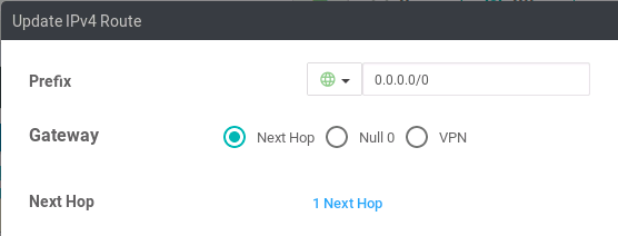
need to do here is define the static default route for this lab. Click the
New IPv4 Route button. Set the Prefix variable to global 0.0.0.0/0.
Then click the Add Next Hop link, and set the address to a Device Specific
variable. Variable names must be unique, and I chose default_next_hop for
this template. The variable value will be defined when you attach the template
to a device. Click the Add button to complete the next hop setting, then
click the Add button again to add the default route to the template. Click
the Save button at the bottom.
Now we get to see part of the usefulness of using templates. From the feature
templates screen, click the three dots on the right side of the
VPN0_1_uplink template, and then click Copy. You are presented with a
dialog box to update the template name and description. I’ll bet you guessed
that I used VPN0_2_uplinks, and you are correct. Click the three dots on the
right side of the row for the new template, then click Edit.
Now we only need to change what is different for this template, which in this case is just adding a second next-hop for the default route for the devices with dual uplinks. Each VPN template can only have a single definition for any particular route (but of course the template can contain definitions for multiple routes). With the traditional Cisco IOS CLI, you would define two static default routes with different next-hops. With the VPN template, we define the single static default route, but with two different next-hops.
Click the pencil icon under the Action section of the default route.
Then click 1 Next Hop.
Since variable names must be unique, change the current name. Remember you will
need to refer to this variable when attaching the template to a device, so make
sure the variable name is meaningful. I am using default_next_hop_1.
Click Add Next Hop and define another variable, default_next_hop_2.
Click Save Changes twice, then click Update.
VPN Interface templates
The VPN template defines the VPN itself, but we need interfaces to attach. The VPN Interface templates describe the configuration of the physical or logical interfaces themselves. This is another area where planning and consideration for your environment is important. Most of your templates should cover the widest and most generic (e.g. most-deployed) options available.
There is a tradeoff between the number of templates and the amount of information that must be entered through variables. To help guide that decision, look at what is common and what is different in what you are trying to do. In this topology, all of the links are common in that they are full-duplex gigabit Ethernet with static IP addressing. Differences include interface names, whether or not they will carry 802.1Q-tagged traffic, and whether they will belong to the transport VPN or a service VPN.
When the interface templates are assigned to a device template, they can only be used once per VPN. This means for devices with dual uplinks, you will need two individual interface templates. To reduce the number of templates, determine what is common across the largest number of your sites. For example, if most of your branch sites are set up so that the first WAN interface always connects to an MPLS L3VPN while the second interface always connects to a public Internet service, you could create a template for each transport type, which is what we will do for this lab.
Add a new feature template, and select CSR1000v and vEdge Cloud device
types. Then click the VPN Interface Ethernet template type. I am naming
this one VPN0_private1. Set the Shutdown to global no, and the
Interface Name to the device-specific variable vpn0_int_private1. Also
set the IPv4 Address to the device-specific variable vpn0_ip_private1.
Set the Tunnel Interface to global on, and the Color to global
private1. Click the Save button at the bottom to finalize the template.
From the Feature Template section, copy the previous template and name it
VPN0_public-internet. Modify all the variables to change from private1
to public-internet.
Device templates
To get an idea where we are going with this and to start seeing the templates in action, we are going to create and apply device templates for our three SD-WAN edges. Device templates are a collection of feature templates. You can also create device templates based on the CLI, which may be useful for transitioning to SD-WAN from a legacy skill set, but it is considered the less-preferred way of configuring devices in this environment.
Device templates are created per device-type so that only features pertaining to that particular device can be configured. However, you can have multiple templates for the same type of device. We are going to create two device templates, one for the vEdge and one for the cEdges in the lab topology.
With this lab topology, we only need these two device templates for now because both of our cEdge sites have dual uplinks. If one site had a single uplink while the other had dual uplinks, we would need two separate device templates to account for this, even though they are the same kind of device. This is another area where careful planning and standardization is to your advantage when rolling out Cisco SD-WAN.
From Configuration > Templates > Device, click the Create Template
button, and select From Feature Template. Choose the vEdge Cloud for
the device model. I am naming this vEdge_single_uplink. For now, the only
settings we need to modify are to change the VPN 0 template to
VPN0_1_uplink and the associated VPN Interface to VPN0_private1. Even
though we won’t be using a VPN 512 interface right now, it still needs to be
specified in the template for a vEdge, so select the factory default, a VPN
interface, and add the default template. Then click the Create button at the
bottom.
Create another device template, and choose CSR1000v. I named this one
CSR1Kv_dual_uplink. With this version of vManage code, the cEdge templates
specify AAA and Cisco-AAA templates, which cannot be used together.
Change the AAA template to None. Set VPN 0 to VPN0_2_uplinks, and
VPN Interface to VPN0_private1. Under Additional VPN 0 Templates, add
a new VPN Interface and set it to VPN0_public-internet. Then click the
Create button at the bottom.
Now we attach the templates to devices. Click the three dots on the right-side
of the vEdge_single_uplink row, and select Attach Devices. Choose
DC1-VE1 from the list and click Attach. At this stage, you have the
option of configuring the variables individually, or exporting and importing
a CSV file. We will configure the devices individually, but you can see how
much quicker it would be to configure your devices using CSV files if you
have more than a handful of edges.
Click the three dots, and select Edit Device Template. Now you are
presented with the variables you created within the feature templates. You
should be able to immediately see how creating good, meaningful variable
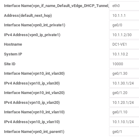
names is very important. The variables and values for DC1-VE1 are:
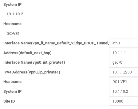
I made a mistake in provisioning where I named the edge DC-VE1 when it
was onboarded instead of DC1-VE1. This is where you can set or correct that
value. Even though the hostname, system IP and site ID have already been set,
these values can be changed, which is why you must re-enter them when you
attach the device template for the first time. Also note that when configuring
interfaces, you must use the full interface name as the device sees it (e.g.
ge0/0 for a vEdge or GigabitEthernet0/0 for a cEdge). Click Update,
and then click Next.
Now you are presented with a ‘pre-provisioning’ screen. You don’t have to do
anything here, and can just click Configure Devices to proceed if you wish.
However, you can also click on any device in the list to view what
configuration will be applied, how it compares to the current configuration,
and set a rollback timer in case the new configuration permanently breaks
communications with the controller. The config diff feature, in particular, is
very nice. After you click Configure Devices, the template is pushed to the
device(s). You can view the progress, and if any errors occur, the
configuration is rolled back and you should be informed as to why the
configuration failed.
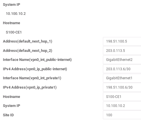
Go back to the device templates section and attach the two cEdges to the CSR1Kv template. These are the values I used for this lab:
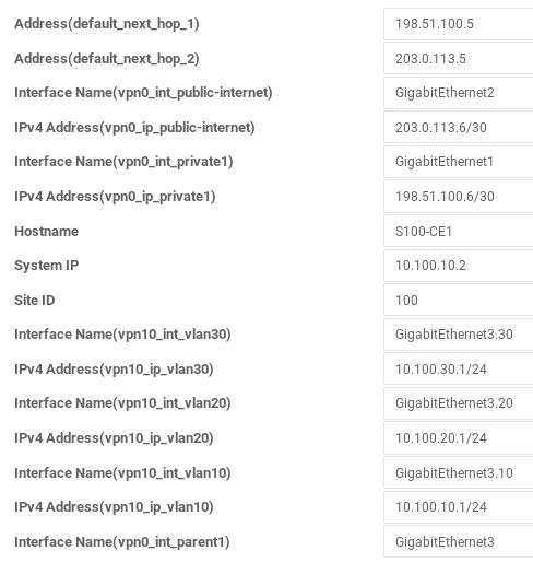
S100-CE1:
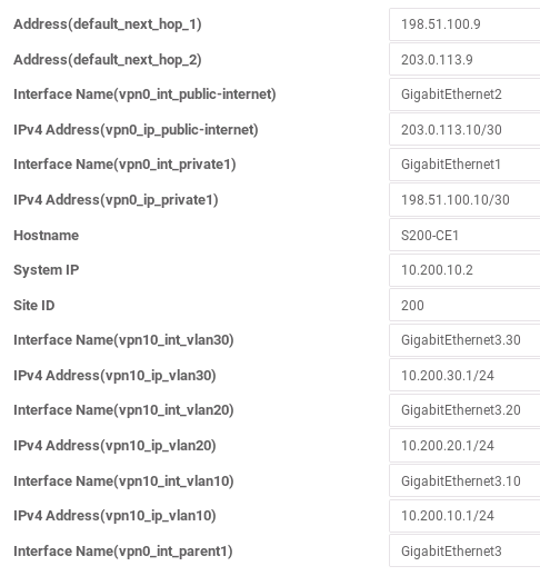
S200-CE1:
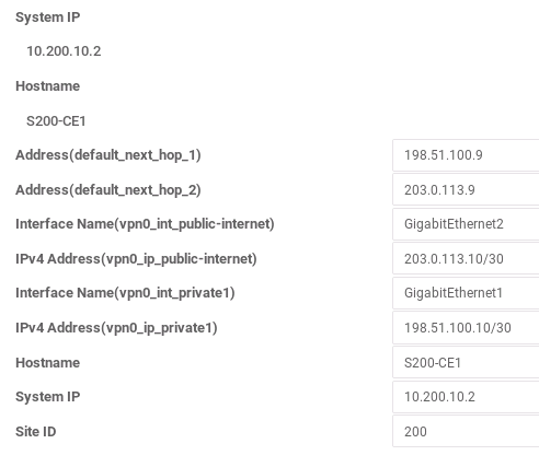
Once the values are entered and the configuration is applied, hopefully everything goes well and all of your devices stay online. At this point, we have essentially replicated what was done during the initial edge device onboarding (refer to the appendix), but with templates. We are now ready to start bringing user traffic into the SD-WAN fabric.
Service VPN
As you have seen, it takes a decent amount of prerequisite work before you can
start passing user traffic across the SD-WAN. Luckily, the basic process of
adding a service VPN is very similar to what we’ve already covered. Service
VPNs carry user traffic, and are any VPN with an ID other than 0 or 512.
As of v19.2, you can have a total of 64 VPNs in a single fabric.
From the template configuration section in vManage, create a new feature
template and select the CSR1000V and vEdge Cloud devices. Choose the
VPN template. For this template, I am naming it VPN10_basic. Set the VPN
to global value 10. Under the Advertise OMP section, set Static and
Connected to global on, and then click the Save button at the bottom.
Next we need to create VPN interface templates for this service VPN. Once again, you need to consider that for each device, you can use a VPN interface template only once per VPN, so if you have multiple interfaces participating in the same VPN on the same device, you need a different interface template for each of them. For this lab, all of our SD-WAN edges have three LAN-facing subinterfaces, so we need three VPN interface templates.
Create a new feature temple, selecting the CSR1000V and vEdge Cloud
devices. Choose the VPN Interface Ethernet template. I named this one
VPN10_int_vlan10. Set the Shutdown value to global on, and the
Interface Name to device-specific variable vpn10_int_vlan10. We are
still using static addresses, so set the IPv4 Address to device-specific
variable vpn10_ip_vlan10.
The last settings we will change for this template for now are under the
Advanced section. We need to change the IP MTU to global 1400 and the
TCP MSS to global 1360. This is sort of a ‘catch-all’ value and is just
fine for the lab, but is something else that needs serious consideration in a
production network. With DMVPN tunnels, these settings were very common. The
standard MTU is 1500, and the edge device must perform packet fragmentation if
the MTU is set lower and the devices attached to the subnet are not modified
accordingly.
In practice, for normal user traffic, this might not be a big deal, especially
for smaller branch offices with low volumes of traffic. Another consideration
with the Cisco SD-WAN architecture is if you are going to use 802.1Q-tagged
subinterfaces (which we will in this lab). When using tagged subinterfaces,
you must either set the parent interface to have an MTU that is at least 4
bytes higher (e.g. 1504), or set all of your subinterfaces to be at least 4
bytes lower. When you set the MTU to 1400 and ensure your attached devices
are also configured accordingly, you account for the overhead of the different
encapsulations (802.1Q, IPsec, etc.).
Copy the template two more times, and change the values for VLANs 20 and
30, respectively.
When using subinterfaces, the parent interface also needs its own template,
and it must belong to VPN 0. You will receive an error when you push out
the template if you have subinterfaces without the parent interface belonging
to VPN 0. Though it is in VPN 0, it will not be sourcing any tunnels and will
not have an IP address assigned. This essentially acts as a placeholder.
You can copy one of the previous templates and change the name to
VPN0_int_parent1. Change the Interface Name to vpn0_int_parent1 and
set the IPv4 Address to default. Also set the IP MTU and TCP MSS values
to default.
Now we can attach the templates to the devices. From the device templates
configuration section, edit the vEdge template. Under VPN 0, add a new VPN
Interface and reference the VPN0_int_parent1 template. Then click the plus
sign next to Service VPN, and select VPN10_basic in the dropdown. Click
VPN Interface three times, and select the three VLAN interface templates.
Now click the Update button to save the device template changes.
You’ll then see the list of devices that require values to be filled for the
variables. Click the three dots on the right-side of the device and select
Edit Device Template. The values for this lab are as follows:
Perform the same set of steps for the cEdge device template. Add the VPN 0
parent interface, the VPN 10 service VPN, and the three subinterfaces.
S100-CE1:
S200-CE1:
Success! Forwarding user traffic
At this point, you should be able to ping any of the .1 or .254 addresses
from both the edge routers and attached switches inside VPN 10.
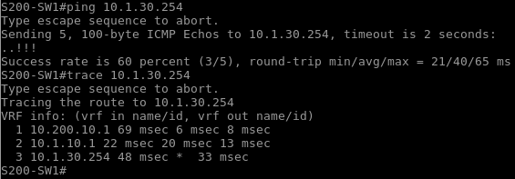
You can see it takes a little more time than you might expect to reach that
IP for the first time. There are many factors that go into this, not the least
of which is the fact that this entire lab is running inside a single EVE-NG
virtual machine. The traceroute shows S200-CE1 as the first hop, then the
underlying transport is completely invisible until it reaches DC1-VE1
(just like an MPLS L3VPN with TTL propagation disabled). In fact, this goes
even deeper than a traditional SP-owned L3VPN because the edge resides behind
a couple of hops within the data center behind the SP-connected edge firewall.
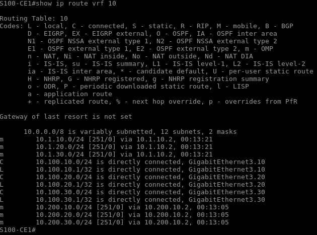
From a cEdge, you can view the VPN routing table as you would like a traditional VRF:
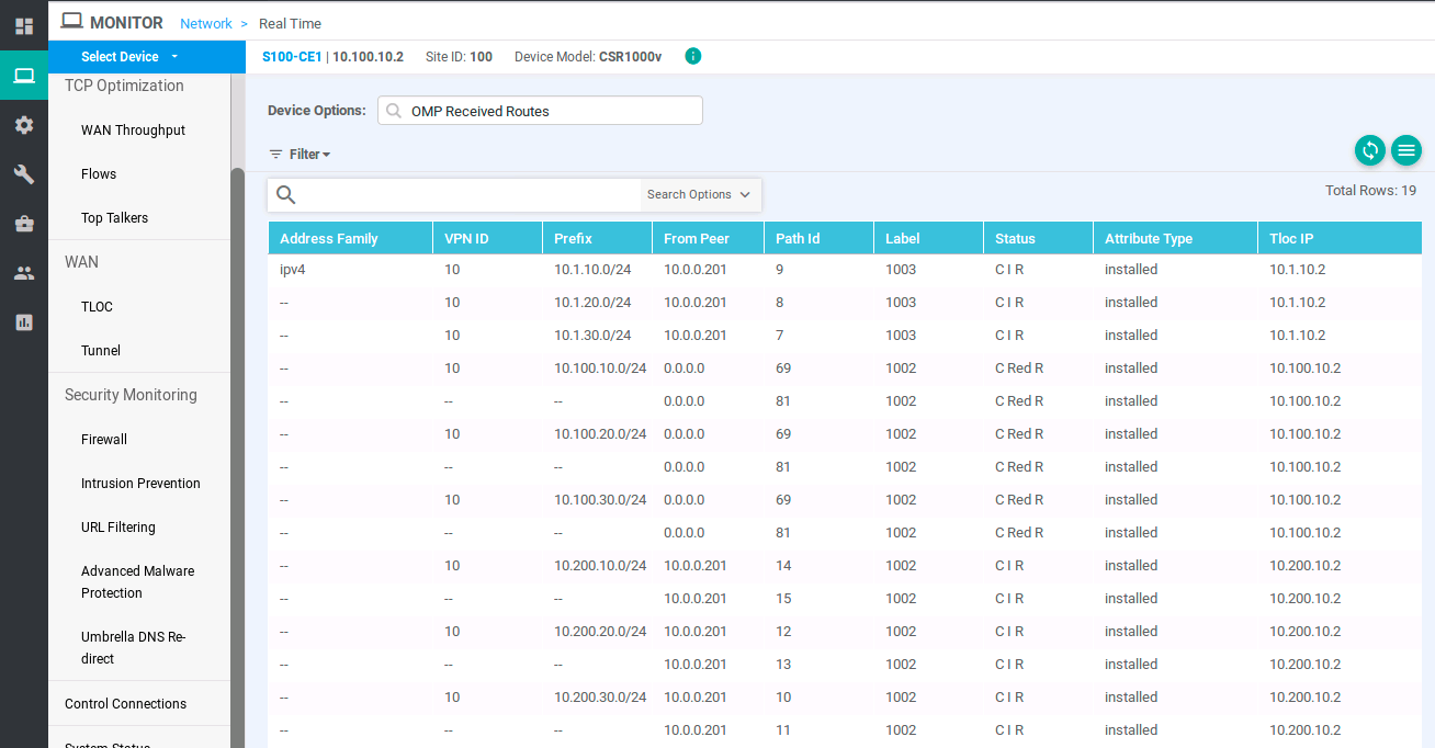
You can get even more details from the command line with various
show sdwan omp commands. But, of course, that’s old-school. You can get to
the same information (and a lot more) through vManage by going to
Monitor > Network > Device > Real Time and select your desired information,
such as OMP Received Routes.
Final thoughts
Like many Cisco products, there is a huge amount of functionality within Cisco’s SD-WAN. Before you can explore that functionality, you have to get over the hurdle of creating a baseline configuration. It was my hope that this post was able to bring you to that point where you now have a working environment and enough initial introduction to the platform to comfortably explore further in your lab. I recommend looking through the official configuration guides, as well as bookmarking the Cisco SD-WAN Community Resources page.
What was covered in this long post is not even the tip of the iceberg. There are so many functional components to the architecture and you really must invest a lot of time to become an expert with this solution. However, there is something in Cisco SD-WAN for everyone from entry-level support to seasoned experts and architects.
As with most all-encompassing technologies, Cisco SD-WAN requires extensive and careful planning and tweaking for a successful deployment. Very large-scale environments have several design and operational implications. For example, I demonstrate adding three interfaces to a VPN. What if you needed to add hundreds of them? Instead of clicking through the web interface, you would be better served by automating this process by utilizing the vManage API (thanks Tim!). Do you need to connect thousands of sites together? How is that going to impact the tunnel capacity of your edge devices? How will you ensure your support staff is able to transition from your legacy environment to operating SD-WAN? These are all questions that your team needs to carefully evaluate before rolling out this technology.
Appendix: Initial Lab Setup
Please refer to the topology image at the top of this post.
If you’re completely new to Cisco SD-WAN or would like to follow along with this post in your own lab, this appendix goes over standing up the controllers and performing initial device onboarding. I decided to put this at the end so that those who are more familiar with the architecture could dive in faster and skip this initial setup, if desired. I thought about breaking this up into a separate post, but I personally like things consolidated whenever possible, and a small Twitter poll agreed with me (very scientific, I know).
In order to run your own self-hosted lab, your Cisco CCO account must have the privileges to generate or access a PnP vBond controller profile, assign devices to your account for licensing, and download the provisioning file (aka serial number file), in addition to being able to download the appropriate software images. If you do not have the appropriate relationship with Cisco (customer, partner, internal employee, etc.) then you won’t have access to these required components to host your own lab. However, you can still learn this Cisco SD-WAN solution and apply the concepts of this article by reserving a DevNet Sandbox. Note: please do not contact me about getting these required resources for your own lab, I am unable to help with that.
Alin Iorguta has a great post on his site poc::v:lab on how to create licenses for your devices, set up the PnP vBond controller profile, and obtain the provisioning file necessary to complete this lab.
The official documentation says that the vBond IP address must be publicly reachable. For the purpose of setting up your own self-hosted lab, this does not have to be true. You just need the IP address of the controller specified in the PnP vBond profile to match what you will set up in the lab environment. In a self-hosted production deployment, the vBond is typically placed on a DMZ and NAT may be used to reach it. For this lab topology, I used static routing at the SP1 and SP2 devices to eliminate NAT in order to keep things simple for now.
Set up the CA
I am using EVE-NG Pro to host the lab environment. The Pro version features
built-in Docker containers, which I will be using to set up the root
Certificate Authority machine. The Cisco SD-WAN trust model is based on X.509
certificates. No device in the SD-WAN fabric can participate without having
valid certificates installed. While I am using a container for this purpose,
if you don’t have the Pro version of EVE-NG, you can use any virtual machine
with OpenSSL installed. You can even use the vManage VM (via the vshell
command) to generate the root certificate, but using a separate device makes
it easier to distribute the certificates later. Using a VM with a GUI (web
browser) also enables you to keep the lab 100% self-contained within the
hypervisor.
Since I am using the eve-gui-server container, I set the startup
configuration to match my lab topology:
ip addr add 10.0.0.10/24 dev eth0 || true
ip route add default via 10.0.0.1 || true
grep -qxF 'PermitRootLogin yes' /etc/ssh/sshd_config || echo 'PermitRootLogin yes' >> /etc/ssh/sshd_config
/etc/init.d/ssh restart
The first two lines set the IP address and default gateway, while the last two lines enable logging into the container via SSH with the root account (which is root / eve by default in EVE-NG). The last lines check the SSH config file to see if root login is enabled, add the appropriate line if it’s not present, and restart the SSH server.
Next, generate the root key and certificate from a command prompt on the CA:
openssl genrsa -out SDWAN.key 2048
openssl req -new -x509 -days 2000 -key SDWAN.key -out SDWAN.pem -sha256 \
    -subj "/C=$A/ST=$B/L=$C/O=$D/CN=$E"
The -subj switch is entirely optional and the $ variables must be
replaced with actual values. $D must match what you specified for the
Organization Name when you created the PnP vBond controller profile. $E
can match $D, but it doesn’t have to. If you don’t add the -subj switch
and include values, you will be asked to enter the values individually, and
the Organization Name must match. The -sha256 switch is also optional.
The OpenSSL documentation goes into more detail if you want to learn
more about the different possible combinations.
The SDWAN.pem file is what will be distributed to and installed on all of
the devices that participate in the SD-WAN fabric, including the controllers
and edge devices (vEdge Cloud and CSR1000v for this lab).
Set up the vBond
Open a console to the vBond VM. The default login for all images in this lab is admin / admin, and starting with 19.2 / 16.12, you must create a new admin password upon first login. Enter an initial ‘skinny’ configuration to assign basic information, and then download and install the root certificate:
conf t
system
 host-name vBond
 system-ip 10.10.0.4
 site-id 10000
 organization-name YOUR-LAB
 vbond 10.10.0.3 local vbond-only
!
vpn 0
 interface ge0/0
  ip address 10.10.0.3/24
  no tunnel-interface
  no shutdown
 ip route 0.0.0.0/0 10.10.0.1
!
commit and-quit

vshell
scp root@10.0.0.10:SDWAN.pem .
exit

request root-cert-chain install /home/admin/SDWAN.pem
The organization-name setting must match what you used in the PnP vBond
profile and be the same across all SD-WAN devices in the fabric. All devices
in the fabric must also know how to reach a vBond. The vBond image is the
same as the vEdge Cloud, so the local vbond-only configuration is how the
VM knows to function as a vBond for the fabric.
In Cisco SD-WAN terms, a VPN is very similar in concept to a VRF, and VPN0
is the transport VPN used on all SD-WAN devices. The configured static route
applies only to VPN0. VPN0 is also what the IPsec and/or GRE tunnels will be
built over. With the ‘skinny’ configuration, we are temporarily disabling the
VPN0 tunnel interface until we configure the vSmart and vManage so that we
don’t run into a ‘chicken-and-the-egg’ problem with trusting certificates.
The vshell command brings you into a bash shell where you can use SCP to
copy the root certificate from the CA machine. After the file is copied, exit
bash, and install the certificate. You can verify the root cert installation
with the show certificate root-ca-cert command.
Set up the vSmart
The initial configuration for the vSmart is very similar to the vBond:
conf t
system
 host-name vSmart
 system-ip 10.0.0.201
 site-id 10000
 organization-name YOUR-LAB
 vbond 10.10.0.3
!
vpn 0
 interface eth0
  ip address 10.0.0.200/24
  no tunnel-interface
  no shutdown
 ip route 0.0.0.0/0 10.0.0.1
!
commit and-quit

vshell
scp root@10.0.0.10:SDWAN.pem .
exit

request root-cert-chain install /home/admin/SDWAN.pem
Set up the vManage
When you first log into the console of the vManage VM, after setting the initial admin password, you are prompted with where you wish to store the data that vManage generates. After selecting the partition, you are asked to format it. When the initialization is complete, the vManage VM reboots. After the system is ready again, you can proceed with the skinny configuration.
conf t
system
 host-name vManage
 system-ip 10.0.0.101
 site-id   10000
 organization-name YOUR-LAB
 vbond 10.10.0.3
!
vpn 0
 interface eth0
  ip address 10.0.0.100/24
  no shutdown
 ip route 0.0.0.0/0 10.0.0.1
!
commit and-quit

vshell
scp root@10.0.0.10:SDWAN.pem .
exit

request root-cert-chain install /home/admin/SDWAN.pem
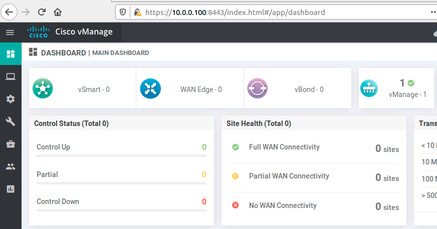
Now use a web browser (from the CA in this lab topology and all further
examples) to log into the vManage web console at https://10.0.0.100:8443.
If the VM has recently rebooted, it may take a few minutes before the web
interface is fully available. You’ll be prompted with a warning about using a
self-signed certificate, which you can ignore since this is just a lab
environment. Login as ‘admin’ with the password you set.
Navigate to Administration > Settings and edit the Organization Name to
match what you’ve been entering everywhere else. Then edit the vBond
setting and enter the vBond address. Finally, since this is a self-contained
lab using self-signed certificates, set the Controller Certificate Authorization setting to Manual. If you had your own PKI with a CA
hierarchy, you could use the Enterprise Root Certificate setting.
Now, from the web browser, go to
https://10.0.0.100/dataservice/system/device/sync/rootcertchain to
request a resync of the vManage database via API call. You may be asked for
the admin password again.
Prepare the controller certificates
Within vManage, navigate to Configuration > Devices > Controllers > Add Controller > vBond. Enter the vBond IP address you’ve been configuring
everywhere else (10.10.0.3 in this topology), along with the admin username
and password. Uncheck Generate CSR. Follow the same steps for adding the
vSmart controller (10.0.0.200 in this lab), leaving the Protocol setting
at the default DTLS and not generating a Certificate Signing Request yet.
Now navigate to Configuration > Certificates > Controllers. For each
controller, click the three dots in the right column and select Generate CSR.
The reason we do it here instead of the previous step is it allows you to save
the CSR as a file. As I download each file, I rename them to vManage.csr,
vBond.csr and vSmart.csr respectively, and move them into the same folder
on the CA machine as the root key and certificate. After you have all three
CSR files, create and sign the device certificates:
openssl x509 -req -in vManage.csr -CA SDWAN.pem -CAkey SDWAN.key \
        -CAcreateserial -out vManage.pem -days 2000 -sha256

openssl x509 -req -in vBond.csr -CA SDWAN.pem -CAkey SDWAN.key \
        -CAcreateserial -out vBond.pem -days 2000 -sha256

openssl x509 -req -in vSmart.csr -CA SDWAN.pem -CAkey SDWAN.key \
        -CAcreateserial -out vSmart.pem -days 2000 -sha256
After the certificates are generated and signed, go to Configuration > Certificates > Controllers and click the Install Certificate button in the
upper-right corner. Install the vManage.pem, vBond.pem and vSmart.pem
files. After successful installation, back on the controller certificate
configuration page, you’ll see certificate serial number listed for each
controller.
Connect the controllers
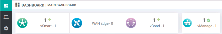
At this point, when you go to the vManage dashboard, you’ll see that vManage knows about itself, and nothing else.
The next step is to enable the VPN0 tunnel interfaces on the three SD-WAN
controllers. Log into the console on both vManage and vSmart and enter these
commands:
conf t
vpn 0
 interface eth0
  tunnel-interface
commit and-quit
Enter these commands on vBond:
conf t
vpn 0
 interface ge0/0
  tunnel-interface
   encapsulation ipsec
commit and-quit
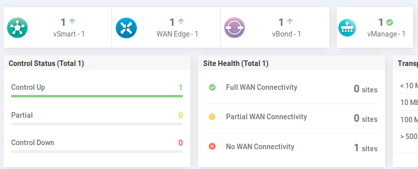
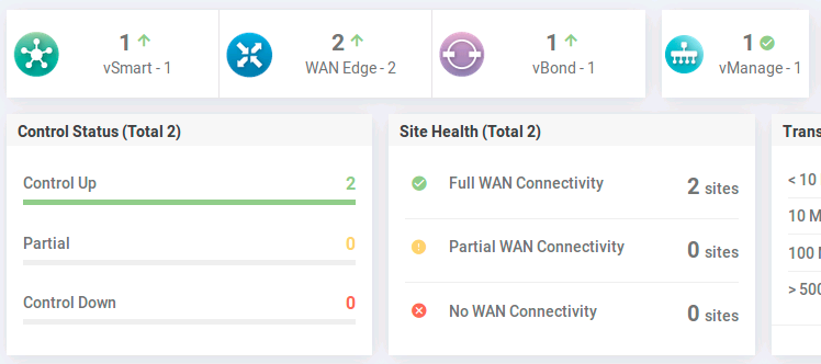
Shortly after, the dashboard updates to reflect the new connectivity:
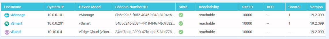
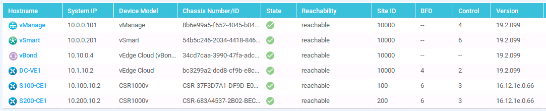
This can be further verified from Monitor > Network, where all three
controllers are shown as reachable:
Upload the WAN Edge List
The final step in preparing the initial controller infrastructure is to upload
the provisioning file you obtained from Cisco earlier. Note once again that
I am unable to assist you in obtaining this. Go to Configuration > Devices
and click Upload WAN Edge List. Select your provisioning file. There is an
option Validate the uploaded vEdge List and send to controllers. In a lab
setting, it is safe to check this box. If you don’t check the box, your
authorized SD-WAN edge devices are uploaded to vManage, but they are in the
invalid state until you change them to staging or valid.
Keeping a device in the invalid state until you are ready to bring it into
the SD-WAN fabric increases security in a production environment. The
controllers essentially ignore any devices in the invalid state. The
staging state allows you to bring the edge device into the fabric, but not
participate in routing. In other words, it will establish control connections
but not transit any user traffic. This is useful in production when you want
to bring a device online, but you’re not yet ready to use it, which might
happen in either a greenfield environment, or when the cutover from the old
WAN environment to the new one will occur remotely.
After uploading the WAN Edge List, you’ll see your devices in `Configuration
Devices`. For each device, you’ll see the chassis number and token value which we’ll use in the next steps. Physical devices have a serial number that does not change, but virtual devices have a token (aka OTP one-time password) that changes each time the WAN Edge List is imported. For example, if you delete a device from the list, then re-upload the provisioning file, that single device will be re-added to the list with the same chassis number, but a different token value.
If you did not check the Validate box when you uploaded the serial file,
you will need to go to Configuration > Certificates > WAN Edge List and
click either Staging or Valid for the edge device under the Validate
column.
Now we are ready to bring our edges onboard!
Edge onboarding
For this lab, I am using a vEdge Cloud v19.2.099 to represent a datacenter
headend router, and cEdge CSR1000v routers running IOS-XE 16.12.1e-SDWAN
code. The IOS-XE SDWAN image removes access to many of the features present
in the regular IOS-XE image. The commands may appear in the CLI, but you
can’t actually use them. Likewise, you’ll see right away that your usual
conf t no longer works (which I think is kind of funny because it works
on the vEdge).
Now when entering configuration mode on a cEdge, you use config-transaction
or config-t. This starts a new candidate configuration (hey, IOS finally
joins the 21st century!). For both vEdge and cEdge, we need to use a skinny
configuration to bring the device online just far enough to be able to
download the root certificate first.
A couple of notes on the cEdge routers. First, starting with IOS-XE 16.12, after you log into the console the first time, you must configure a user with a level 15 privilege otherwise you will lock yourself out of the router. For a physical IOS-XE device, this means doing the complete time-consuming password recovery procedure if you get locked out.
Second, it is important to get the root certificate installed before bringing up the tunnel interfaces. If the cEdge connects to the vManage without the proper root certificate, it gets stuck with a failed Certificate Signing Request and you will have to start over which includes wiping the lab router, and deleting and re-adding the edge from vManage. It’s best to just get it right the first time.
For the vEdge Cloud image that this lab uses, there is an issue with QEMU and
the virtio vNIC where 802.1Q-tagged traffic does not get transmitted or
received. If you are using QEMU with a vEdge (such as with EVE-NG), set the
vNIC to E1000 to work around this issue.
cEdge
To bring the Site 100 cEdge device into the fabric, log into the console and
add the initial skinny configuration (also known as a bootstrap configuration,
though this specific term has a different meaning within the context of Cisco
SD-WAN, which is why I call it ‘skinny’).
config-transaction
!
hostname S100-CE1
username admin priv 15 secret admin
no ip domain lookup
!
system
 system-ip 10.100.10.2
 site-id 100
 organization-name YOUR-LAB
 vbond 10.10.0.3
 exit
!
ip route 0.0.0.0 0.0.0.0 198.51.100.5
ip route 0.0.0.0 0.0.0.0 203.0.113.5
interface GigabitEthernet1
 no shutdown
 ip address 198.51.100.6 255.255.255.252
interface GigabitEthernet2
 no shutdown
 ip address 203.0.113.6 255.255.255.252
!
commit
end
Although the system stanza is new, the remaining configuration items are
standard Cisco IOS. With this minimal configuration in place, you should now
be able to reach the CA machine to download and install the root certificate:
copy scp://root@10.0.0.10:/SDWAN.pem bootflash:

request platform software sdwan root-cert-chain install bootflash:SDWAN.pem
You can verify the certificate installation with the show sdwan cert root
command. You will see that many of the verification commands that you can
issue on a vEdge can be done on a cEdge by adding sdwan to the front.
After the root certificate is installed, you can configure the tunnel interfaces:
config-transaction
!
interface Tunnel1
 no shutdown
 ip unnumbered GigabitEthernet1
 tunnel source GigabitEthernet1
 tunnel mode sdwan
exit
interface Tunnel2
 no shutdown
 ip unnumbered GigabitEthernet2
 tunnel source GigabitEthernet2
 tunnel mode sdwan
exit
sdwan
 interface GigabitEthernet1
  tunnel-interface
   encapsulation ipsec
   color private1
  exit
 interface GigabitEthernet2
  tunnel-interface
   encapsulation ipsec
   color public-internet
  exit
 exit
!
commit
end
Now we need to activate the cEdge. From vManage, go to Configuration > Devices and choose a CSR1000v from your list. Click the three dots on the
right-side of the row, and select Generate Bootstrap Configuration. Choose
the Cloud-Init option. We will use the uuid and otp values in the next
cEdge CLI command:
request platform software sdwan vedge_cloud activate chassis-number UUID token OTP
Upon success, you’ll shortly see a message on the cEdge console about the
vmanage-admin successfully authenticating. You’ll see a few more console
messages, and after approximately two minutes, you should see messages about
OMPD connecting to vSmart. After the cEdge is fully connected, you’ll see it
in the vManage dashboard:
You can further verify from vManage by going to Monitor > Network:
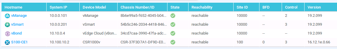
You can also verify from the cEdge with show sdwan control connections:
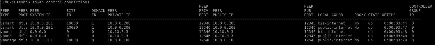
Connections from the cEdge to the vSmart and vBond are established over both transport links (SP1 and SP2).
Follow the same process for the second cEdge.
config-transaction
!
hostname S200-CE1
username admin priv 15 secret admin
no ip domain lookup
!
system
 system-ip 10.200.10.2
 site-id 200
 organization-name YOUR-LAB
 vbond 10.10.0.3
 exit
!
ip route 0.0.0.0 0.0.0.0 198.51.100.9
ip route 0.0.0.0 0.0.0.0 203.0.113.9
interface GigabitEthernet1
 no shutdown
 ip address 198.51.100.10 255.255.255.252
interface GigabitEthernet2
 no shutdown
 ip address 203.0.113.10 255.255.255.252
!
commit
end

copy scp://root@10.0.0.10:/SDWAN.pem bootflash:

request platform software sdwan root-cert-chain install bootflash:SDWAN.pem

config-transaction
!
interface Tunnel1
 no shutdown
 ip unnumbered GigabitEthernet1
 tunnel source GigabitEthernet1
 tunnel mode sdwan
exit
interface Tunnel2
 no shutdown
 ip unnumbered GigabitEthernet2
 tunnel source GigabitEthernet2
 tunnel mode sdwan
exit
sdwan
 interface GigabitEthernet1
  tunnel-interface
   encapsulation ipsec
   color private1
  exit
 interface GigabitEthernet2
  tunnel-interface
   encapsulation ipsec
   color public-internet
  exit
 exit
!
commit
end

request platform software sdwan vedge_cloud activate chassis-number UUID token OTP
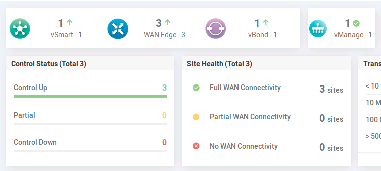
Give it a couple of minutes, and you should see it online:
vEdge
Finally, we’ll onboard the datacenter vEdge for this simple topology. The process is very similar.
conf t
system
 host-name DC1-VE1
 system-ip 10.1.10.2
 site-id 10000
 organization-name YOUR-LAB
 vbond 10.10.0.3
!
vpn 0
 interface ge0/0
  ip address 10.1.1.2/30
  no tunnel-interface
  no shutdown
 ip route 0.0.0.0/0 10.1.1.1
!
commit and-quit

vshell
scp root@10.0.0.10:SDWAN.pem .
exit

request root-cert-chain install /home/admin/SDWAN.pem

conf t
vpn 0
 interface ge0/0
  tunnel-interface
   encapsulation ipsec
commit and-quit

request activate vedge_cloud chassis-number UUID token OTP
Monitor > Network:
At this point, the controllers and edges are all communicating with each other and you are essentially at a clean slate. Now jump to the beginning of this post and configure some templates!
Miscellaneous information
Software versions:
- Viptela: v19.2.099
- IOS-XE: v16.12.1e-SDWAN
SD-WAN System IPs:
- vManage: 10.0.0.101
- vBond: 10.10.0.4
- vSmart: 10.0.0.201
- DC1-VE1: 10.1.10.2
- S100-CE1: 10.100.10.2
- S200-CE1: 10.200.10.2
Interface IPs:
- DC1-FW1:
- g0/0 > 10.1.0.1 /30
- g0/1 > 10.10.0.1 /24
- g0/2 > 198.51.100.2 /30
- g0/3 > 203.0.113.2 /30
- DC1-SW1:
- VLAN 1 > 10.0.0.1 /24
- VLAN 2 > 10.1.0.1 /30
- VLAN 10 > 10.1.1.1 /30
- DC1-SW2:
- VLAN 10 > 10.1.10.254 /24
- VLAN 20 > 10.1.20.254 /24
- VLAN 30 > 10.1.30.254 /24
- DC1-VE1:
- ge0/0 > 10.1.1.2 /30
- ge0/1.10 > 10.1.10.1 /24
- ge0/1.20 > 10.1.20.1 /24
- ge0/1.30 > 10.1.30.1 /24
- S100-CE1:
- g1 > 198.51.100.6 /30
- g2 > 203.0.113.6 /30
- g3.10 > 10.100.10.1 /24
- g3.20 > 10.100.20.1 /24
- g3.30 > 10.100.30.1 /24
- S100-SW1:
- VLAN 10 > 10.100.10.254 /24
- VLAN 20 > 10.100.20.254 /24
- VLAN 30 > 10.100.30.254 /24
- S200-CE1:
- g1 > 198.51.100.10 /30
- g2 > 203.0.113.10 /30
- g3.10 > 10.200.10.1 /24
- g3.20 > 10.200.20.1 /24
- g3.30 > 10.200.30.1 /24
- S200-SW1:
- VLAN 10 > 10.200.10.254 /24
- VLAN 20 > 10.200.20.254 /24
- VLAN 30 > 10.200.30.254 /24
- SP1:
- g0/0 > 198.51.100.1 /30
- g0/1 > 198.51.100.5 /30
- g0/2 > 198.51.100.9 /30
- g0/3 > 192.0.2.1 /30
- SP2:
- g0/0 > 203.0.113.1 /30
- g0/1 > 203.0.113.5 /30
- g0/2 > 203.0.113.9 /30
- g0/3 > 192.0.2.2 /30
Routing:
- SP1:
- 10 /8 > 198.51.100.2
- 203.0.113.0 /24 > 192.0.2.2
- SP2:
- 10 /8 > 203.0.113.2
- 198.51.100.0 /24 > 192.0.2.1
- DC1-FW1:
- 10 /8 > 10.1.0.1
- 0 /0 > 198.51.100.1
- 0 /0 > 203.0.113.1
- DC1-SW1:
- 0 /0 > 10.1.0.2
- S100-CE1:
- VPN0: 0 /0 > 198.51.100.5
- VPN0: 0 /0 > 203.0.113.5
- S200-CE1:
- VPN0: 0 /0 > 198.51.100.9
- VPN0: 0 /0 > 203.0.113.9
Thank you for reading!