YA-NAT: Yet Another Network Address Translation Post
Table of Contents
NAT can be a very confusing topic. In the real world, NAT is most frequently performed on firewalls and load balancers, but the Cisco Routing & Switching curriculum has you configure NAT on routers. It is easy to get confused by the addressing terminology and everyone explains it a little differently. NAT44 (translating one IPv4 address to another) is a part of the CCIE RSv5 lab exam and my lack of preparedness for this topic was part of my downfall for my first lab attempt in 2018. I should say, I thought I was prepared but was proven wrong. This post attempts to rectify that.
There are already a lot of great resources available for tackling this topic (some listed at the end), which is why I titled this “Yet Another…” (also as a tongue-in-cheek reference to the many standards and protocols that begin with YA). However, as mentioned, everyone seems to explain NAT just a little bit different. In this post, I cover terminology and several different NAT44 use cases.
I intend this post to be understandable for everyone from the CCNA through CCNP and CCIE levels. NAT is a huge topic (hence the length of this post), but even still, it is not possible to cover every kind of scenario and use case, though I have examined several here. As you get deeper into configuring networking equipment, you’ll begin to see how similar it can be to programming or creating scripts in that you must think through operational order and how things flow. There are usually multiple ways to accomplish the same goal, and you can get very creative with how you solve specific problems.
There are some NAT topics not covered here such as NAT with IPsec, stateful NAT with HSRP, NAT ALG (Application Layer Gateways), CGN (carrier-grade NAT), translation between IPv4 and IPv6, and some others. This post is meant to provide a solid foundation for solving essential NAT use cases with Cisco IOS. Most of these configurations work with IOS-XE as well.
Most of the topics and my explanations build on each other, so I recommend you read everything in order for the first time. I put some source links and a configuration mind map in the Resources section, along with a PDF version of this post.
Please expand the Table of Contents for an overview of the covered scenarios.
Introduction
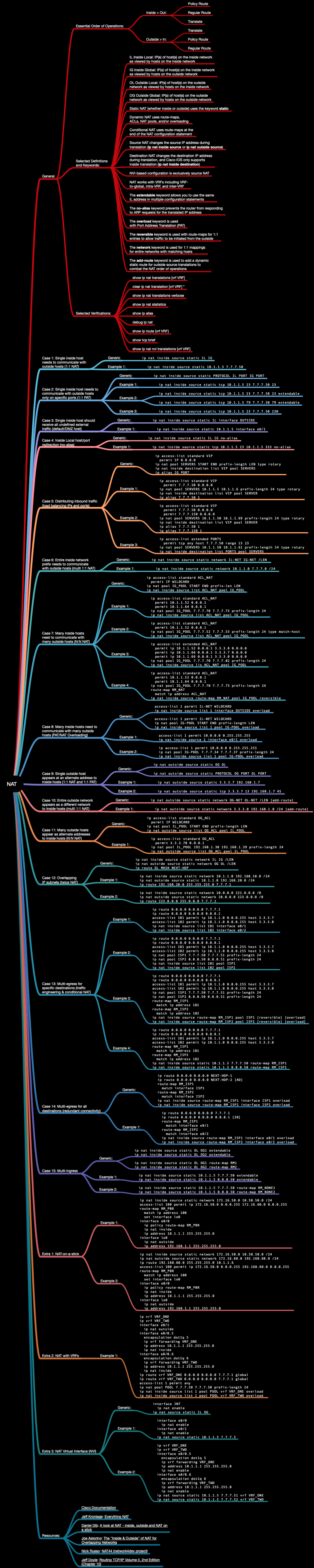
Let’s start with terminology. This is perhaps the most confusing part of understanding NAT. I have found that fully comprehending the terminology is very essential to understanding the corresponding configurations, and indeed being able to work through the packet flow in your mind. The four terms for IP address types with regard to NAT are Inside Local (IL), Inside Global (IG), Outside Local (OL), and Outside Global (OG).
IL and OG are the easiest to understand, in my opinion. IL is most frequently your local private IP address, and OG is most frequently a public IP address belonging to someone else. There are exceptions, of course, both in terms of ownership and that neither address must be strictly public or private in terms of RFC1918 addressing, but this is the most common scenario when people think of NAT.
For IG, there is confusion over the “inside” part because the address usually is part of the address space on the “outside” interface. OL is possibly the most confusing term and may be the one most difficult to understand because frequently the OG and OL addresses are the same. Paraphrasing from Joe Astorino, the four address types can be understood as:
- Inside Local: IP(s) of host(s) on the inside network as viewed by hosts on the inside network.
- Inside Global: IP(s) of host(s) on the inside network as viewed by hosts on the outside network.
- Outside Local: IP(s) of host(s) on the outside network as viewed by hosts on the inside network.
- Outside Global: IP(s) of host(s) on the outside network as viewed by hosts on the outside network.
Using these definitions, you can see why from the IL point of view, the OL and OG addresses are frequently the same, which can be confusing. I also like how Scott Morris described it on CLN: “Inside and Outside have to do with where the address originated before you touched it (merely a perspective thing). Local = what it looks like to your network, Global = what it looks like to everyone else […] What does the IP look like now? And what do I want it to look like when I’m done.”
In any scenario, you will need to define at least one inside and one outside interface (with the exception of NAT Virtual Interface (NVI) configuration). Additionally, you need to keep in mind the Cisco NAT order of operations. When moving from the inside interface to the outside, routing is done first, then translation. From the outside interface to the inside, translation occurs first, then routing. This has different kinds of routing implications as we’ll see.
When configuring ip nat statements, with ip nat inside source the inside
interface is subject to translation. As traffic passes through the NAT to the
outside interface, the packet is routed to the destination (i.e. the interface
toward the destination is chosen) and the source IP in the packet is translated
from IL to IG. Return traffic is destined to the IG which is first translated
from the IG to the IL and then routed toward the IL.

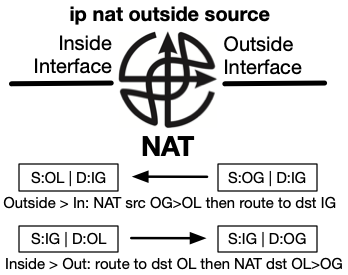
Likewise, with ip nat outside source, the outside interface is subject to
translation. As traffic passes through the NAT to the inside interface, the
source IP address in the packet is translated from OG to OL, then the packet is
routed toward the destination which is the OG address unless other translation
mappings are configured (which is frequent). Return traffic is destined to the
OL address which is routed first, then translated to the OG address as it exits.
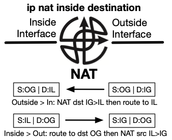
There is also ip nat inside destination which translates the inside
destination address as it passes through the NAT. In Cisco IOS, this
functionality is typically used for load distribution. As traffic passes
through the outside interface to the inside, the destination address is
translated from IG to IL then routed to the IL address. Return traffic is
routed to the destination OG address and the source IL address is translated
back to the IG address.
Is the translation occurring on the outside or inside? Is the source address being translated, or the destination? This becomes easier to understand with some example situations. Some of the use cases overlap slightly, so I recommend going through all of them.
Case 1: Single inside host needs to communicate with outside hosts (1:1 NAT)
The following topology is used for the next several use cases.
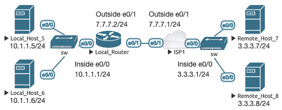
The following base NAT configuration is applied to LR to define the inside and outside interfaces used in the next several cases:
Local_Router(config)# interface e0/0
Local_Router(config-if)# ip nat inside
Local_Router(config)# interface e0/1
Local_Router(config-if)# ip nat outside
In this most basic scenario, LH5 is a device on our inside network with a private IP address that needs to communicate with RH7, which is a device on the outside network with a public IP address. RH7 knows how to reach the 7.7.7.0/24 subnet because it is public, but does not know how to reach private IP addresses outside of its local network. To build the scenario, all hosts are Cisco routers with routing disabled, with LR and ISP1 as the respective default gateways. LR has a default route to ISP1.
In this scenario, only the single inside host needs to communicate with the outside world. Since LH5 has a default gateway assigned, and LR has a default route, technically LH5 can communicate with RH7 already. A better way to phrase this then might be to say RH7 needs to communicate back to LH5. RH7 will receive a ping sent from LH5, but will not know how to reach LH5’s private IP address to send the reply. This configuration enables bidirectional communications:
Local_Router(config)# ip nat inside source static 10.1.1.5 7.7.7.50
This configuration makes it so that hosts on the outside network can communicate with LH 10.1.1.5 by referring to it as 7.7.7.50.
Local_Router# show ip nat translations
Pro Inside global      Inside local       Outside local      Outside global
--- 7.7.7.50           10.1.1.5           ---                ---

Remote_Host_7# ping 7.7.7.50
Type escape sequence to abort.
Sending 5, 100-byte ICMP Echos to 7.7.7.50, timeout is 2 seconds:
!!!!!
Success rate is 100 percent (5/5), round-trip min/avg/max = 1/1/1 ms

Local_Router# show ip nat translations
Pro Inside global      Inside local       Outside local      Outside global
icmp 7.7.7.50:4        10.1.1.5:4         3.3.3.7:4          3.3.3.7:4
--- 7.7.7.50           10.1.1.5           ---                ---
The first show command on LR displays the initial static translation. Next,
RH7 pings the IG address 7.7.7.50. When the ICMP ping reaches LR on the outside
interface, it translates the destination IP address in the packet from 7.7.7.50
to 10.1.1.5 and forwards it from the outside interface to the inside. The
source IP address 3.3.3.7 remains the same during translation. When LH5 replies
(or if LH5 initiates the ping), the destination IP address remains 3.3.3.7 and
LR5 selects the appropriate outgoing interface and changes the source from
10.1.1.5 to 7.7.7.50 as it is forwarded to ISP1. When RH7 receives the packet,
it knows nothing of LH5’s true private IP address. Only LR is aware that
anything was changed in transit, no other devices in the path from source to
destination even know that NAT occurred.
Case 2: Single inside host needs to communicate with outside hosts only on specific ports (1:1 PAT)
In Case 1, all ports were statically mapped from a single IL host to an IG address. What if you wish to have only one or more ports open, and not all ports? Let’s modify the mapping from Case 1 so that only TCP port 23 is mapped:
Local_Router(config)# ip nat inside source static tcp 10.1.1.5 23 7.7.7.50 23
The static mapping is verified:
Local_Router# show ip nat translations
Pro Inside global      Inside local       Outside local      Outside global
tcp 7.7.7.50:23        10.1.1.5:23        ---                ---
Now we telnet from RH8 and view the NAT table again:
Remote_Host_8# telnet 7.7.7.50
Trying 7.7.7.50 … Open
Local_Host_5#

Local_Router# show ip nat translations
Pro Inside global      Inside local       Outside local      Outside global
tcp 7.7.7.50:23        10.1.1.5:23        3.3.3.8:35403      3.3.3.8:35403
tcp 7.7.7.50:23        10.1.1.5:23        ---                ---
I have enabled the ip finger service on LH5. Let’s try to telnet to that port
from RH8 and see what happens:
Remote_Host_8# telnet 7.7.7.50 79
Trying 7.7.7.50, 79 …
% Connection refused by remote host
It does not get through because only TCP port 23 is mapped. What if we want to
map both telnet and finger to the single inside host? The extendable keyword
allows you to map multiple entries to the same IL address. We’ll see another
example of this later.
Local_Router(config)# ip nat inside source static tcp 10.1.1.5 23 7.7.7.50 23 extendable
Local_Router(config)# ip nat inside source static tcp 10.1.1.5 79 7.7.7.50 79 extendable

Remote_Host_8# telnet 7.7.7.50 79
Trying 7.7.7.50, 79 … Open

Local_Router# show ip nat translations
Pro Inside global      Inside local       Outside local      Outside global
tcp 7.7.7.50:23        10.1.1.5:23        3.3.3.8:60238      3.3.3.8:60238
tcp 7.7.7.50:23        10.1.1.5:23        ---                ---
tcp 7.7.7.50:79        10.1.1.5:79        3.3.3.8:20852      3.3.3.8:20852
tcp 7.7.7.50:79        10.1.1.5:79        ---                ---
You can also perform port address translation (PAT) using this same method. Let’s make LH5’s telnet port reachable from the outside on port 230:
Local_Router(config)# ip nat inside source static tcp 10.1.1.5 23 7.7.7.50 230

Remote_Host_8# telnet 7.7.7.50
Trying 7.7.7.50 …
% Connection refused by remote host

Remote_Host_8# telnet 7.7.7.50 230
Trying 7.7.7.50, 230 … Open
Local_Host_5#

Local_Router# show ip nat translations
Pro Inside global      Inside local       Outside local      Outside global
tcp 7.7.7.50:230       10.1.1.5:23        3.3.3.8:28437      3.3.3.8:28437
tcp 7.7.7.50:230       10.1.1.5:23        ---                ---
Case 3: Single inside host should receive all undefined external traffic (default/DMZ host)
With this use case, any external traffic destined for the outside interface is automatically forwarded and translated to a single inside host, unless other specific mappings are in place. Before this configuration, any external host can telnet to LR at 7.7.7.2 (LR’s outside interface), as long as the host can reach that IP address. With the following configuration, all outside traffic with a destination address of 7.7.7.2 is translated to 10.1.1.5.
Local_Router(config)# ip nat inside source static 10.1.1.5 interface Ethernet0/1

Local_Router# show ip nat translations
Pro Inside global      Inside local       Outside local      Outside global
--- 7.7.7.2            10.1.1.5           ---                ---

Remote_Host_8# telnet 7.7.7.2
Trying 7.7.7.2 … Open
Local_Host_5#

Local_Router# show ip nat translations
Pro Inside global      Inside local       Outside local      Outside global
tcp 7.7.7.2:23         10.1.1.5:23        3.3.3.8:50466      3.3.3.8:50466
--- 7.7.7.2            10.1.1.5           ---                ---
Notice what happens if an inside host tries the same thing:
Local_Host_6# telnet 7.7.7.2
Trying 7.7.7.2 … Open
Local_Router#

Local_Router# show ip nat translations
Pro Inside global      Inside local       Outside local      Outside global
--- 7.7.7.2            10.1.1.5           ---                ---
When coming from the outside interface in, NAT is done first, routing second. So when the request is coming from RH7 on the outside, LR translates it and sends it to LH5. When coming from the inside interface out, routing is done first, then NAT. LH6 is coming from the inside interface, and there are no applicable NAT mappings.
Combining the concepts together, let’s create some more mappings to further demonstrate the NAT default host. The previous NAT configuration from this case is still present.
Local_Router(config)# ip nat inside source static tcp 10.1.1.5 23 7.7.7.50 230 extendable
Local_Router(config)# ip nat inside source static tcp 10.1.1.6 23 7.7.7.50 2300 extendable
Local_Router(config)# ip nat inside source static tcp 10.1.1.6 23 7.7.7.2 23000 extendable
Local_Router(config)# ip nat inside source static 10.1.1.6 7.7.7.60
IG address 7.7.7.50 will forward port 230 to port 23 on IL address 10.1.1.5. IG address 7.7.7.50 will also forward port 2300 to port 23 on IL address 10.1.1.6. IG 7.7.7.2 will forward port 23000 to port 23 on IL address 10.1.1.6. Finally, there is a 1:1 mapping of IL address 10.1.1.6 to IG address 7.7.7.60. Several different connection attempts are made to demonstrate the concepts:
Remote_Host_7# telnet 7.7.7.2
Trying 7.7.7.2 … Open
Local_Host_5#

Remote_Host_7# telnet 7.7.7.2 230
Trying 7.7.7.2, 230 …
% Connection refused by remote host

Remote_Host_7# telnet 7.7.7.2 23000
Trying 7.7.7.2, 23000 … Open
Local_Host_6#

Remote_Host_7# telnet 7.7.7.50
Trying 7.7.7.50 …
% Connection refused by remote host

Remote_Host_7# telnet 7.7.7.50 230
Trying 7.7.7.50, 230 … Open
Local_Host_5#

Remote_Host_7# telnet 7.7.7.50 2300
Trying 7.7.7.50, 2300 … Open
Local_Host_6#

Remote_Host_7# telnet 7.7.7.60
Trying 7.7.7.60 … Open
Local_Host_6#

Remote_Host_7# telnet 7.7.7.60 79
Trying 7.7.7.60, 79 … Open

Local_Router# show ip nat translations
Pro Inside global      Inside local       Outside local      Outside global
tcp 7.7.7.2:23         10.1.1.5:23        3.3.3.7:16105      3.3.3.7:16105
tcp 7.7.7.50:230       10.1.1.5:23        3.3.3.7:38670      3.3.3.7:38670
tcp 7.7.7.50:230       10.1.1.5:23        ---                ---
tcp 7.7.7.2:230        10.1.1.5:230       3.3.3.7:15245      3.3.3.7:15245
--- 7.7.7.2            10.1.1.5           ---                ---
tcp 7.7.7.2:23000      10.1.1.6:23        ---                ---
tcp 7.7.7.2:23000      10.1.1.6:23        3.3.3.7:54492      3.3.3.7:54492
tcp 7.7.7.60:23        10.1.1.6:23        3.3.3.7:22353      3.3.3.7:22353
tcp 7.7.7.50:2300      10.1.1.6:23        3.3.3.7:63863      3.3.3.7:63863
tcp 7.7.7.50:2300      10.1.1.6:23        ---                ---
tcp 7.7.7.60:79        10.1.1.6:79        3.3.3.7:24256      3.3.3.7:24256
--- 7.7.7.60           10.1.1.6           ---                ---
- First pass: telnet port 23 is forwarded to LH5.
- Second pass: port 230 is indeed forwarded to LH5 as demonstrated in the NAT mapping table, but there is no service running on that port on LH5.
- Third pass: port 23000 is specifically mapped to LH6 23, but all other unmapped ports get forwarded to the default host LH5.
- Fourth pass: we know that telnet is running on both LH5 and LH6, but the mappings are explicitly for outside ports 230 and 2300 so the connection is refused and there is no corresponding entry in the NAT table.
- Fifth pass: telnet to IG 7.7.7.50 port 230 is forwarded to LH5.
- Sixth pass: telnet to IG 7.7.7.50 port 2300 is forwarded to LH6.
- Seventh and eighth passes: telnet ports 23 and 79 to IG 7.7.7.60 are forwarded to LH6 because it’s a 1:1 IL/IG mapping.
Case 4: Inside Local host/port redirection (no-alias)
When traffic is coming from the outside, you can redirect both hosts and ports
as the previous use cases have demonstrated. What if you want to redirect the
destination host or port from one IL address to another? When you configure ip nat inside source static you will still be creating an IG address mapping
which the router will claim by automatically creating an IP alias. You can
translate from one IL address or port to another without the router trying to
claim the IL address as an IG address with the no-alias keyword.
In the previous examples, RH7 and RH8 did not know how to reach LH5 and LH6 because they are using private IP addresses that are not routable on the Internet. For this demonstration, I have temporarily configured a static route on ISP1 for 10.1.1.0/24 with the next hop 7.7.7.2 so that RH7 and RH8 can reach LH5 and LH6 without NAT.
With the following configuration, when an outside host tries to connect to
10.1.1.5 on port 333, it is redirected to 10.1.1.5 on port 23. Without the
no-alias keyword, LR would try to claim the existing 10.1.1.5 IP address.
Local_Router(config)# ip nat inside source static tcp 10.1.1.5 23 10.1.1.5 333 no-alias

Local_Router# show ip nat translations
Pro Inside global      Inside local       Outside local      Outside global
tcp 10.1.1.5:333       10.1.1.5:23        ---                ---
Here’s what happens when RH7 tries to telnet to LH5 on port 333:
Remote_Host_7# telnet 10.1.1.5 333
Trying 10.1.1.5, 333 … Open
Local_Host_5#
Now let’s change the mapping of just the IL address to LH6:
Local_Router(config)# ip nat inside source static tcp 10.1.1.6 23 10.1.1.5 333 no-alias

Local_Router# show ip nat translations
Pro Inside global      Inside local       Outside local      Outside global
tcp 10.1.1.5:333       10.1.1.6:23        ---                ---
The IL has been changed to LH6, but the IG is LH5, which we still do not want the router to claim for itself. Let’s try to telnet from RH7 to LH5 again:
Remote_Host_7# telnet 10.1.1.5 333
Trying 10.1.1.5, 333 … Open
Local_Host_6#
Previously, I configured a static route on ISP1 to demonstrate the concepts. What if you need to perform the previous translations, but the remote hosts have no route to the ultimate destination? You can combine multiple layers of NAT to achieve this. I have modified the topology slightly to account for this by inserting a new “Internal” router on the inside network:
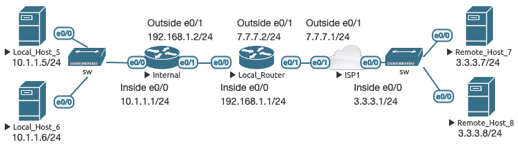
Internal has a static default route to LR, which has a static default route to ISP1. LR knows how to reach the 10.1.1.0/24 network through the Internal router. However, RH7 and RH8 do not know how to reach 10.1.1.0/24 or 192.168.1.0/24. I have configured a static 1:1 mapping on LR to map IG address 7.7.7.50 to IL address 10.1.1.5, and a mapping on Internal similar to before where 10.1.1.5 port 333 redirects to port 23:
Local_Router(config)# ip nat inside source static 10.1.1.5 7.7.7.50

Internal(config)# ip nat inside source static tcp 10.1.1.5 23 10.1.1.5 333 no-alias
RH7 telnets to 7.7.7.50 port 333. The packet’s destination is translated from 7.7.7.50 to 10.1.1.5 at LR and routed toward 192.168.1.2. When the packet reaches Internal, the port is translated from 333 to 23 and routed to 10.1.1.5.
Remote_Host_7# telnet 7.7.7.50 333
Trying 7.7.7.50, 333 … Open
Local_Host_5#

Local_Router# show ip nat translations
Pro Inside global      Inside local       Outside local      Outside global
tcp 7.7.7.50:333       10.1.1.5:333       3.3.3.7:25175      3.3.3.7:25175
--- 7.7.7.50           10.1.1.5           ---                ---

Internal# show ip nat translations
Pro Inside global      Inside local       Outside local      Outside global
tcp 10.1.1.5:333       10.1.1.5:23        3.3.3.7:25175      3.3.3.7:25175
tcp 10.1.1.5:333       10.1.1.5:23        ---                ---
Case 5: Distributing inbound traffic (load balancing IPs and ports)
Traditional load balancers have many options to distribute traffic combined
with other features like determining host liveliness as a prerequisite for pool
membership. Cisco IOS provides some rudimentary traffic distribution through
the ip nat inside destination configuration where you can forward incoming
requests for a particular service to a pool of destinations. You can forward
ranges of ports as well. We are using the original topology without the
Internal router for this case:
A standard ACL is used to define a virtual IP address (VIP). We will also use a new configuration to define a pool of IP addresses used just for NAT.
Local_Router(config)# ip access-list standard VIP
Local_Router(config-std-nacl)# permit 7.7.7.50 0.0.0.0
Local_Router(config)# ip nat pool SERVERS 10.1.1.5 10.1.1.6 prefix-length 24 type rotary
Local_Router(config)# ip nat inside destination list VIP pool SERVERS
Local_Router(config)# ip alias 7.7.7.50 1
With this configuration, the ACL defines the VIP. The NAT pool defines the
starting and ending IP range, though we only have two consecutive hosts in this
particular range. The type rotary keyword indicates that each new request
should be sent to the next member in the pool. The ip nat inside destination
statement says that the ACL representing IG addresses should be translated to
IL addresses within the referenced pool.
Finally, with this configuration, IOS does not automatically create an alias entry like it does with the previous use cases. You must identify the IG address(es) and a destination port. One entry is required per VIP, and the port can be any acceptable value—it does not need to be the same as your intended destination service. The single referenced port (1 in this example) serves to create the alias that actually works as a placeholder for all ports.
Here are the results of RH7 connecting to the VIP 7.7.7.50:
Remote_Host_7# telnet 7.7.7.50
Trying 7.7.7.50 … Open
Local_Host_5#

Remote_Host_7# telnet 7.7.7.50
Trying 7.7.7.50 … Open
Local_Host_6#

Local_Router# show ip alias
Address Type             IP Address     Port
Interface                7.7.7.2
Alias                    7.7.7.50       1
Interface                10.1.1.1

Local_Router# show ip nat translations
Pro Inside global      Inside local       Outside local      Outside global
tcp 7.7.7.50:23        10.1.1.5:23        3.3.3.7:53257      3.3.3.7:53257
tcp 7.7.7.50:23        10.1.1.6:23        3.3.3.7:64386      3.3.3.7:64386
I have created secondary IP addresses on LH5 (10.1.1.50-59) and LH6 (10.1.1.60- 69) to make things more interesting. I have added the following configuration to LR:
Local_Router(config)# ip access-list standard VIP
Local_Router(config-std-nacl)# permit 7.7.7.50 0.0.0.0
Local_Router(config-std-nacl)# permit 7.7.7.150 0.0.0.0
Local_Router(config)# ip nat pool SERVERS 10.1.1.50 10.1.1.69 prefix-length 24 type rotary
Local_Router(config)# ip alias 7.7.7.150 1
I’ve added a second VIP (and associated alias) and changed the server pool to 10.1.1.50-10.1.1.69. Here’s what happens when I telnet from RH7 over and over again:
Local_Router# show ip nat translations
Pro Inside global      Inside local       Outside local      Outside global
tcp 7.7.7.50:23        10.1.1.50:23       3.3.3.7:21747      3.3.3.7:21747
tcp 7.7.7.150:23       10.1.1.50:23       3.3.3.7:31177      3.3.3.7:31177
tcp 7.7.7.50:23        10.1.1.51:23       3.3.3.7:35127      3.3.3.7:35127
tcp 7.7.7.150:23       10.1.1.51:23       3.3.3.7:40246      3.3.3.7:40246
tcp 7.7.7.50:23        10.1.1.52:23       3.3.3.7:29739      3.3.3.7:29739
tcp 7.7.7.50:23        10.1.1.53:23       3.3.3.7:28545      3.3.3.7:28545
tcp 7.7.7.50:23        10.1.1.54:23       3.3.3.7:63771      3.3.3.7:63771
tcp 7.7.7.50:23        10.1.1.55:23       3.3.3.7:21784      3.3.3.7:21784
tcp 7.7.7.50:23        10.1.1.56:23       3.3.3.7:41610      3.3.3.7:41610
tcp 7.7.7.50:23        10.1.1.57:23       3.3.3.7:58774      3.3.3.7:58774
tcp 7.7.7.50:23        10.1.1.58:23       3.3.3.7:49432      3.3.3.7:49432
tcp 7.7.7.50:23        10.1.1.59:23       3.3.3.7:62948      3.3.3.7:62948
tcp 7.7.7.50:23        10.1.1.60:23       3.3.3.7:32954      3.3.3.7:32954
tcp 7.7.7.50:23        10.1.1.61:23       3.3.3.7:40711      3.3.3.7:40711
tcp 7.7.7.150:23       10.1.1.62:23       3.3.3.7:46215      3.3.3.7:46215
tcp 7.7.7.150:23       10.1.1.63:23       3.3.3.7:60925      3.3.3.7:60925
tcp 7.7.7.150:23       10.1.1.64:23       3.3.3.7:54644      3.3.3.7:54644
tcp 7.7.7.150:23       10.1.1.65:23       3.3.3.7:11142      3.3.3.7:11142
tcp 7.7.7.150:23       10.1.1.66:23       3.3.3.7:17924      3.3.3.7:17924
tcp 7.7.7.150:23       10.1.1.67:23       3.3.3.7:55602      3.3.3.7:55602
tcp 7.7.7.150:23       10.1.1.68:23       3.3.3.7:35769      3.3.3.7:35769
tcp 7.7.7.150:23       10.1.1.69:23       3.3.3.7:39327      3.3.3.7:39327
The entries aren’t timestamped, but first I connected to 7.7.7.50 twelve times. You can see the IL address go from 10.1.1.50 - 10.1.1.61. I then started connecting to 7.7.7.150. The next available pool member was then referenced (10.1.1.62) until the end of the pool was reached. The next connection started at the beginning of the pool (10.1.1.50).
There are a couple of different ways that you can get creative with this
configuration using extended ACLs. However, within the ip nat inside destination statements, a single ACL can only be matched with a single NAT
pool, but different ACLs can reference the same NAT pool. Here is a variation
of the configuration where I use an extended ACL to permit any source to send
traffic to the VIP 7.7.7.50 only on TCP ports 13 through 23. I also shortened
the pool to reduce the connection attempts needed to demonstrate the concept:
Local_Router(config)# ip access-list extended PORTS
Local_Router(config-ext-nacl)# permit tcp any host 7.7.7.50 range 13 23
Local_Router(config)# ip nat pool SERVERS 10.1.1.58 10.1.1.61 prefix-length 24 type rotary
Local_Router(config)# ip nat inside destination list PORTS pool SERVERS
I then connect several times from RH7 on TCP ports 13 and 23. You can see how it still load balances across the IPs defined in the pool. I also tried connecting to TCP ports 79 and 113, and was refused due to the extended ACL (not all attempts are shown).
Remote_Host_7# telnet 7.7.7.50
 Trying 7.7.7.50 … Open
 Local_Host_5#

Remote_Host_7# telnet 7.7.7.50 113
 Trying 7.7.7.50, 113 …
 % Connection refused by remote host

Remote_Host_7# telnet 7.7.7.50 79
 Trying 7.7.7.50, 79 …
 % Connection refused by remote host

Remote_Host_7# telnet 7.7.7.50 13
 Trying 7.7.7.50, 13 … Open

Local_Router# show ip nat translations
Pro Inside global      Inside local       Outside local      Outside global
tcp 7.7.7.50:13        10.1.1.58:13       3.3.3.7:24860      3.3.3.7:24860
tcp 7.7.7.50:23        10.1.1.58:23       3.3.3.7:18560      3.3.3.7:18560
tcp 7.7.7.50:23        10.1.1.58:23       3.3.3.7:52849      3.3.3.7:52849
tcp 7.7.7.50:13        10.1.1.59:13       3.3.3.7:47168      3.3.3.7:47168
tcp 7.7.7.50:13        10.1.1.59:13       3.3.3.7:65279      3.3.3.7:65279
tcp 7.7.7.50:23        10.1.1.59:23       3.3.3.7:58859      3.3.3.7:58859
tcp 7.7.7.50:13        10.1.1.60:13       3.3.3.7:63563      3.3.3.7:63563
tcp 7.7.7.50:23        10.1.1.60:23       3.3.3.7:55627      3.3.3.7:55627
tcp 7.7.7.50:13        10.1.1.61:13       3.3.3.7:44056      3.3.3.7:44056
tcp 7.7.7.50:23        10.1.1.61:23       3.3.3.7:14317      3.3.3.7:14317
Case 6: Entire inside network prefix needs to communicate with outside hosts (multi 1:1 NAT)
If you have many internal hosts residing in the same IP subnet that you would
like to create 1:1 mappings for, you can use the ip nat inside source static network command as a shortcut instead of having to create each mapping
individually. The host IP addresses are automatically matched. The following
command maps the entire 10.1.1.0/24 IL to 7.7.7.0/24 IG. Following is the
initial mapping table. The verbose keyword shows you when a mapping was
created and how long it will remain in the table (0 = infinity).
Local_Router(config)# ip nat inside source static network 10.1.1.0 7.7.7.0 /24

Local_Router# show ip nat translations verbose
Pro Inside global      Inside local       Outside local      Outside global
--- 7.7.7.0            10.1.1.0           ---                ---
    create 00:04:53, use 00:04:53 timeout:0,
    flags:
static, network, use_count: 0, entry-id: 1, lc_entries: 0
Try to ping the IG address of LH5 from RH7:
Remote_Host_7# ping 7.7.7.5
Type escape sequence to abort.
Sending 5, 100-byte ICMP Echos to 7.7.7.5, timeout is 2 seconds:
.....
Success rate is 0 percent (0/5)
You might think it times out because 10.1.1.5 has not initiated any outbound sessions yet, and therefore there is no mapping in the NAT table. That was my first thought, too. The real reason this ping fails is because the upstream router from the device performing NAT does not have an ARP entry for 7.7.7.5 yet. When you initiate an outbound session from 10.1.1.5 (a ping, for example), when the NAT router performs the translation and forwards the packet upstream, the upstream router (ISP1) creates an ARP entry for 7.7.7.5. To demonstrate this, I will create a static ARP entry on ISP1 that maps 7.7.7.5 to LR’s e0/1 interface, show the LR NAT table, ping from RH7 to LH5’s IG address, and show the LR NAT table again. This is with RH7 initiating initial communications, not LH5.
ISP1(config)# arp 7.7.7.5 aabb.cc00.0e10 arpa

Local_Router# show ip nat translations
Pro Inside global      Inside local       Outside local      Outside global
--- 7.7.7.0            10.1.1.0           ---                ---

Remote_Host_7# ping 7.7.7.5
Type escape sequence to abort.
Sending 5, 100-byte ICMP Echos to 7.7.7.5, timeout is 2 seconds:
!!!!!
Success rate is 100 percent (5/5), round-trip min/avg/max = 1/1/2 ms

Local_Router# show ip nat translations
Pro Inside global      Inside local       Outside local      Outside global
icmp 7.7.7.5:0         10.1.1.5:0         3.3.3.7:0          3.3.3.7:0
--- 7.7.7.5            10.1.1.5           ---                ---
--- 7.7.7.0            10.1.1.0           ---                ---
The static ARP entry on ISP1 enables communications because when RH7 pings
7.7.7.5, it is routed to ISP1, which knows that it can reach that IP address
with an Ethernet frame destined to the MAC address of LR’s e0/1 interface. When
LR receives the packet destined to 7.7.7.5, it translates it to 10.1.1.5 and
creates a dynamic IP alias entry in addition to NAT mappings. Within the NAT
table, the static network mapping remains indefinitely, but the dynamic
mappings (both the ICMP mapping and general 7.7.7.5 > 10.1.1.5 mapping) will
expire with the normal translation timeout (which you can verify with show ip nat translations verbose and set with ip nat translation timeout SECONDS).
Once again, without the static ARP entry that was placed on ISP1, the inside host must first generate the outbound traffic in order to establish the ARP entry in the upstream router beyond the NAT. While that dynamic ARP entry exists in the upstream router, any outside hosts that can route to 7.7.7.5 can reach 10.1.1.5. When the upstream dynamic ARP entry times out, outside hosts will be unable to reach 10.1.1.5 until the ARP entry is re-established.
To further demonstrate the dynamic 1:1 mapping, I initiated a ping from LH6 to RH7 using LH6’s secondary IP address of 10.1.1.66:
Local_Router# show ip nat translations
Pro Inside global      Inside local       Outside local      Outside global
icmp 7.7.7.5:0         10.1.1.5:0         3.3.3.7:0          3.3.3.7:0
--- 7.7.7.5            10.1.1.5           ---                ---
icmp 7.7.7.66:1        10.1.1.66:1        3.3.3.7:1          3.3.3.7:1
--- 7.7.7.66           10.1.1.66          ---                ---
--- 7.7.7.0            10.1.1.0           ---                ---

Local_Router# show ip alias
address Type             IP Address      Port
Interface                7.7.7.2
Dynamic                  7.7.7.5
Dynamic                  7.7.7.66
Interface                10.1.1.1
Case 7: Many inside hosts need to communicate with many outside hosts (N:N NAT)
With this use case, several inside hosts (IL, defined by ACL) need to communicate with many outside hosts defined with an IG NAT pool. The number of IL hosts mapped inside the ACL does not need to match the number of IG addresses in the NAT pool, though these are still dynamic 1:1 mappings. If the IL ACL references more hosts than the IG NAT pool contains, when all IG addresses become used a new IL > IG mapping cannot occur until an old one times out.
Local_Router(config)# ip access-list standard ACL_NAT
Local_Router(config-std-nacl)# permit 10.1.1.52 0.0.0.1
Local_Router(config-std-nacl)# permit 10.1.1.64 0.0.0.1
Local_Router(config)# ip nat pool IG_POOL 7.7.7.70 7.7.7.72 prefix-length 24
Local_Router(config)# ip nat inside source list ACL_NAT pool IG_POOL

Local_Router# show ip nat translations
Immediately after this configuration, the NAT table is empty. Pinging from 10.1.1.5 fails, as is expected:
Local_Host_5# ping 3.3.3.7
Type escape sequence to abort.
Sending 5, 100-byte ICMP Echos to 3.3.3.7, timeout is 2 seconds:
.....
Success rate is 0 percent (0/5)
However, from LH5, pinging from 10.1.1.52 and 10.1.1.53 works because they are defined in the ACL. Likewise, pinging from LH6 from 10.1.1.64 works, but when pinging from 10.1.1.65 these are the results:
Local_Host_6# ping 3.3.3.7 source 10.1.1.65
Type escape sequence to abort.
Sending 5, 100-byte ICMP Echos to 3.3.3.7, timeout is 2 seconds:
Packet sent with a source address of 10.1.1.65
.U.U.
Success rate is 0 percent (0/5)
ICMP unreachable. Here’s the LR NAT table:
Local_Router# show ip nat translations
Pro Inside global      Inside local       Outside local      Outside global
icmp 7.7.7.70:3        10.1.1.52:3        3.3.3.7:3          3.3.3.7:3
--- 7.7.7.70           10.1.1.52          ---                ---
icmp 7.7.7.71:4        10.1.1.53:4        3.3.3.7:4          3.3.3.7:4
--- 7.7.7.71           10.1.1.53          ---                ---
icmp 7.7.7.72:1        10.1.1.64:1        3.3.3.7:1          3.3.3.7:1
--- 7.7.7.72           10.1.1.64          ---                ---
The pool is filled due to the previous three pings from 10.1.1.52, .53, and .64. After at least one translation has timed out, the ping from 10.1.1.65 will work:
Local_Router# show ip nat translations
Pro Inside global      Inside local       Outside local      Outside global
icmp 7.7.7.71:5        10.1.1.65:5        3.3.3.7:5          3.3.3.7:5
--- 7.7.7.71           10.1.1.65          ---                ---
You can use this kind of configuration to map an entire IL subnet into IG
addresses just like with Case 6 by making the ACL and NAT pool cover entire
subnets (/24 for example). The difference is that the IG addresses are handed
out as they are used, whereas with the Case 6 configuration, the IL and IG host
addresses always match. You can force the host matching behavior by adding the
type match-host keyword to the NAT pool definition, but you must ensure your
ACL matches accordingly. If we change the NAT pool to the following
configuration and try to ping from 10.1.1.52, it does not work:
Local_Router(config)# ip nat pool IG_POOL 7.7.7.70 7.7.7.72 prefix-length 24 type match-host

Local_Host_5# ping 3.3.3.7 source 10.1.1.52
Type escape sequence to abort.
Sending 5, 100-byte ICMP Echos to 3.3.3.7, timeout is 2 seconds:
Packet sent with a source address of 10.1.1.52
U.U.U
Success rate is 0 percent (0/5)
But if we change the pool to match the ACL (or vice-versa), it does work:
Local_Router(config)# ip nat pool IG_POOL 7.7.7.52 7.7.7.53 prefix-length 24 type match-host

Local_Router# show ip nat translations
Pro Inside global      Inside local       Outside local      Outside global
icmp 7.7.7.52:8        10.1.1.52:8        3.3.3.7:8          3.3.3.7:8
--- 7.7.7.52           10.1.1.52          ---                ---
icmp 7.7.7.53:9        10.1.1.53:9        3.3.3.7:9          3.3.3.7:9
--- 7.7.7.53           10.1.1.53          ---                ---
With the Case 6 configuration, you must match an entire network. With the Case 7 configuration, you can match on arbitrary lengths and optionally match the hosts. Also, like just about any other configuration that references an ACL, we can get more specific by using an extended ACL. In the following example, I have restored the pool to its original state, and replaced the standard ACL with an extended ACL. NAT will be performed only when 10.1.1.52 or .53 communicates with 3.3.3.8, and 10.1.1.66 and .67 will be translated only when communicating with 3.3.3.7 or .8.
Local_Router(config)# ip nat pool IG_POOL 7.7.7.70 7.7.7.82 prefix-length 24
Local_Router(config)# ip access-list extended ACL_NAT
Local_Router(config-ext-nacl)# permit ip 10.1.1.52 0.0.0.1 3.3.3.8 0.0.0.0
Local_Router(config-ext-nacl)# permit ip 10.1.1.66 0.0.0.1 3.3.3.7 0.0.0.0
Local_Router(config-ext-nacl)# permit ip 10.1.1.66 0.0.0.1 3.3.3.8 0.0.0.0

Local_Host_5# ping 3.3.3.7 source 10.1.1.52
Type escape sequence to abort.
Sending 5, 100-byte ICMP Echos to 3.3.3.7, timeout is 2 seconds:
Packet sent with a source address of 10.1.1.52
....
Success rate is 0 percent (0/5)

Local_Host_5# ping 3.3.3.8 source 10.1.1.52
Type escape sequence to abort.
Sending 5, 100-byte ICMP Echos to 3.3.3.8, timeout is 2 seconds:
Packet sent with a source address of 10.1.1.52
!!!!!
Success rate is 100 percent (5/5), round-trip min/avg/max = 1/1/3 ms

Local_Host_6# ping 3.3.3.7 source 10.1.1.67
Type escape sequence to abort.
Sending 5, 100-byte ICMP Echos to 3.3.3.7, timeout is 2 seconds:
Packet sent with a source address of 10.1.1.67
!!!!!
Success rate is 100 percent (5/5), round-trip min/avg/max = 1/1/1 ms

Local_Host_6# ping 3.3.3.7 source 10.1.1.68
Type escape sequence to abort.
Sending 5, 100-byte ICMP Echos to 3.3.3.7, timeout is 2 seconds:
Packet sent with a source address of 10.1.1.68
.....
Success rate is 0 percent (0/5)

Local_Host_6# ping 3.3.3.8 source 10.1.1.67
Type escape sequence to abort.
Sending 5, 100-byte ICMP Echos to 3.3.3.8, timeout is 2 seconds:
Packet sent with a source address of 10.1.1.67
!!!!!
Success rate is 100 percent (5/5), round-trip min/avg/max = 1/1/1 ms

Local_Host_6# ping 3.3.3.8 source 10.1.1.66
Type escape sequence to abort.
Sending 5, 100-byte ICMP Echos to 3.3.3.8, timeout is 2 seconds:
Packet sent with a source address of 10.1.1.66
!!!!!
Success rate is 100 percent (5/5), round-trip min/avg/max = 1/1/2 ms

Local_Router# show ip nat translations
Pro Inside global      Inside local       Outside local      Outside global
--- 7.7.7.70           10.1.1.52          ---                ---
icmp 7.7.7.72:9        10.1.1.66:9        3.3.3.8:9          3.3.3.8:9
--- 7.7.7.72           10.1.1.66          ---                ---
icmp 7.7.7.71:6        10.1.1.67:6        3.3.3.7:6          3.3.3.7:6
icmp 7.7.7.71:8        10.1.1.67:8        3.3.3.8:8          3.3.3.8:8
--- 7.7.7.71           10.1.1.67          ---                ---
Pinging to 3.3.3.7 from 10.1.1.52 and to 3.3.3.7 from 10.1.1.68 fails because they are explicitly outside the extended ACL and therefore fail to have NAT performed.
You can also perform a similar configuration for Case 7 using a route-map which references the ACL:
Local_Router(config)# ip access-list standard ACL_NAT
Local_Router(config-std-nacl)# permit 10.1.1.52 0.0.0.1
Local_Router(config-std-nacl)# permit 10.1.1.64 0.0.0.1
Local_Router(config)# ip nat pool IG_POOL 7.7.7.70 7.7.7.72 prefix-length 24
Local_Router(config)# route-map RM_NAT
Local_Router(config-route-map)# match ip address ACL_NAT
Local_Router(config)# ip nat inside source route-map RM_NAT pool IG_POOL   reversible
The above configuration is functionally the same as the first configuration of
Case 7. The reversible keyword creates 1:1 mappings that remain once
inside>out communications are established which allows outside traffic to come
back in. The difference with using route-maps is that you have more options
because you can have multiple route-map clauses referenced within the single
NAT statement. Traffic selected by the first matching clause in the route-map
is what gets translated. Additionally, with a route-map you select the outgoing
interface, as we will see in Case 14.
Case 8: Many inside hosts need to communicate with many outside hosts (PAT/NAT Overloading)
All previous use cases demonstrated 1:1 mappings, whether static or dynamic, and whether for entire IP addresses or just individual ports. Case 8 represents the most common use case for NAT44 (and indeed what most people think of if you simply say “NAT” without further qualification). With port address translation, also known as NAT overloading, dynamic IL to IG mappings occur by translating ports as well as IP addresses. This allows more IL addresses to be mapped to fewer IG addresses. Potentially thousands of IL IP addresses can be mapped to a single IG address.
There are many different ways to configure NAT overloading. The keyword in all
cases is overload at the end of the ip nat inside source statement. In each
case, first configure an ACL to match the desired traffic to be translated. We
will stick to standard ACLs here, but as Case 7 demonstrated, you can use
extended ACLs to create more specific translation criteria. We explore using
route-maps in later use cases. The standard ACL I configured matches all
10.0.0.0/8 source IP addresses as the IL address.
Local_Router(config)# access-list 1 permit 10.0.0.0 0.255.255.255
Interface example:
Local_Router(config)# ip nat inside source list 1 interface e0/1 overload
I added 3.3.3.70-79 and 3.3.3.80-89 to RH7 and RH8, respectively, then initiated a telnet session to port 13 on 3.3.3.70 and 80 from LH5, and to 3.3.3.71 and 81 from LH6. The NAT mappings on LR show different source ports mapped with different IL addresses being mapped to the same IG address, whereas all previous use cases showed a strictly 1:1 mapping.
Local_Router# show ip nat translations
Pro Inside global      Inside local       Outside local      Outside global
tcp 7.7.7.2:26795      10.1.1.5:26795     3.3.3.70:13        3.3.3.70:13
tcp 7.7.7.2:54860      10.1.1.5:54860     3.3.3.80:13        3.3.3.80:13
tcp 7.7.7.2:14108      10.1.1.6:14108     3.3.3.81:13        3.3.3.81:13
tcp 7.7.7.2:23210      10.1.1.6:23210     3.3.3.71:13        3.3.3.71:13
Now let’s remove the previous NAT mapping and define one based on a pool. By using a NAT pool, you can specify the IG addresses. You can configure a single IG address by specifying the same starting and ending address in the pool, or multiple contiguous addresses. You can use non-contiguous IG addresses by defining multiple pools, but remember that you are limited in associating a single ACL with a single pool only.
Local_Router(config)# ip nat pool IG_POOL 7.7.7.34 7.7.7.37 prefix-length 24
Local_Router(config)# ip nat inside source list 1 pool IG_POOL overload

Local_Router# show ip nat translations
Pro Inside global      Inside local       Outside local      Outside global
tcp 7.7.7.35:30708     10.1.1.5:30708     3.3.3.73:13        3.3.3.73:13
tcp 7.7.7.35:51294     10.1.1.5:51294     3.3.3.75:13        3.3.3.75:13
tcp 7.7.7.35:28577     10.1.1.6:28577     3.3.3.82:13        3.3.3.82:13
tcp 7.7.7.35:53833     10.1.1.6:53833     3.3.3.86:13        3.3.3.86:13
I am not sure how the IG addresses are chosen from the pool. When I did several requests in a row, the same IG was chosen. I spent some time unsuccessfully researching to see if I could find out how the IG address is selected. I then I tried a few connections again, and this time a different IG address was selected:
Local_Router# show ip nat translations
Pro Inside global      Inside local       Outside local      Outside global
tcp 7.7.7.36:32921     10.1.1.5:32921     3.3.3.70:13        3.3.3.70:13
tcp 7.7.7.36:46217     10.1.1.6:46217     3.3.3.86:13        3.3.3.86:13
You could use the type match-host keyword on the NAT pool configuration, but
I can’t imagine any practical reason to do this (I could see it being a good
CCIE lab troubleshooting task, though). If you add this keyword to the NAT pool
configuration, overloading still occurs, but the translation does not take
place unless an IL host that matches the last octet of the NAT pool definition
initiates a session. After that, non-matching IL hosts can be translated.
Local_Router(config)# ip nat pool IG_POOL 7.7.7.5 7.7.7.5 prefix-length 24 type match-host

Local_Host_6# telnet 3.3.3.86 13
Trying 3.3.3.86, 13 …
% Destination unreachable; gateway or host down

Local_Host_5# telnet 3.3.3.70 13
Trying 3.3.3.70, 13 … Open

Local_Host_6# telnet 3.3.3.86 13
Trying 3.3.3.86, 13 … Open

Local_Router# show ip nat translations
Pro Inside global      Inside local       Outside local      Outside global
tcp 7.7.7.5:39781      10.1.1.5:39781     3.3.3.70:13        3.3.3.70:13
tcp 7.7.7.5:60713      10.1.1.6:60713     3.3.3.86:13        3.3.3.86:13
I mentioned that you can associate a single ACL with a single NAT pool only.
While you can use multiple ACLs with the same NAT pool, the traffic selected by
the ACL must be unambiguous to the NAT pool. For example, you could not have
access-list 1 permit 10.0.0.0 and access-list 2 permit 10.0.0.0 mapped to
the same NAT pool. IOS will allow you to configure this with separate ip nat inside source statements, but translation will fail because it is not clear
which ACL is the source.
If you want to use multiple non-contiguous IG addresses defined across multiple NAT pools, you will need to adjust your ACLs accordingly. For example, you could specify that 10.0.0.0/9 uses one pool, and 10.128.0.0/9 uses another pool. Likewise, you could define extended ACLs and specify that certain destinations use one pool, while other destinations use a different pool.
Case 9: Single outside host appears at an alternate address to inside hosts (1:1 NAT and 1:1 PAT)
In this use case, an outside host knows how to reach the inside host’s real IP address, but the inside host should believe it is communicating with a different host. This is the reverse of Case 1 where the inside knows how to reach the outside, but the outside does not know how to reach the inside. This case is often used during temporary IP address migrations of individual servers.
In our topology, I have temporarily configured a static route on ISP1 so that hosts behind ISP1 can reach 10.1.1.0/24 via LR without NAT. I have configured LR so that when RH7 tries to communicate with any hosts on the inside network, its IP address is translated from 3.3.3.7 to 192.168.1.7. Inside hosts have no specific route to 192.168.1.7 so they use the default route.
Local_Router(config)# ip nat outside source static 3.3.3.7 192.168.1.7

Local_Router# show ip nat translations
Pro Inside global      Inside local       Outside local      Outside global
--- ---                ---                192.168.1.7        3.3.3.7

Remote_Host_7# telnet 10.1.1.5 13
Trying 10.1.1.5, 13 … Open

Local_Router# debug ip nat
NAT: s=3.3.3.7->192.168.1.7, d=10.1.1.5 [53116]
NAT: s=10.1.1.5, d=192.168.1.7->3.3.3.7 [30072]

Local_Router# show ip nat translations
Pro Inside global      Inside local       Outside local      Outside global
--- ---                ---                192.168.1.7        3.3.3.7
tcp 10.1.1.5:13        10.1.1.5:13        192.168.1.7:44905  3.3.3.7:44905

Local_Host_5# telnet 192.168.1.7 13
Trying 192.168.1.7, 13 … Open

Local_Router# debug ip nat
NAT: s=10.1.1.5, d=192.168.1.7->3.3.3.7 [40659]
NAT: s=3.3.3.7->192.168.1.7, d=10.1.1.5 [55163]

Local_Router# show ip nat translations
Pro Inside global      Inside local       Outside local      Outside global
--- ---                ---                192.168.1.7        3.3.3.7
tcp 10.1.1.5:53630     10.1.1.5:53630     192.168.1.7:13     3.3.3.7:13
You can see that when RH7 telnets to LH5 on port 13, the source IP address is translated from 3.3.3.7 to 192.168.1.7 and then routed to 10.1.1.5. When LH5 replies, the reverse happens and the destination 192.168.1.7 is translated back to 3.3.3.7 and therefore LH5 believes RH7 exists at 192.168.1.7. Likewise in the second example where LH5 initiates the communication, LR uses its default route to reach 192.168.1.7, and then sees the NAT mapping and translates 192.168.1.7 to 3.3.3.7 before forwarding the traffic on. Outside > in = NAT first, then route. Inside > out = route first, then NAT.
There is another way to demonstrate the Cisco NAT order of operations. I have
added a second link between LR and ISP1 on e0/2 and configured LR as 8.8.8.2/24
and ISP1 as 8.8.8.1/24. On LR, I configured e0/2 with ip nat outside and
added a static route 192.168.1.0/24 > 8.8.8.1. LR’s default route points to
ISP1 at 7.7.7.1, and 192.168.1.0/24 specifically points to ISP1 at 8.8.8.1.
ISP1 does not have a default route, and LR is the only router in the topology
that knows anything about 192.168.1.0/24.
From LH5, I perform two different traceroutes to RH7. One using RH7’s real address which is reached via LR’s default route, and one using RH7’s translated address, which is reached via LR’s specific route to 192.168.1.0/24. In both cases, the replies to LH5 appear to come from the translated IP address 192.168.1.7, though they take different paths through the network.
Local_Host_5# traceroute 3.3.3.7
Type escape sequence to abort.
Tracing the route to 3.3.3.7
VRF info: (vrf in name/id, vrf out name/id)
  1 10.1.1.1 0 msec 0 msec 0 msec
  2 7.7.7.1 1 msec 0 msec 1 msec
  3 192.168.1.7 1 msec *  2 msec

Local_Host_5# traceroute 192.168.1.7
Type escape sequence to abort.
Tracing the route to 192.168.1.7
VRF info: (vrf in name/id, vrf out name/id)
  1 10.1.1.1 2 msec 1 msec 1 msec
  2 8.8.8.1 1 msec 0 msec 1 msec
  3 192.168.1.7 2 msec *  1 msec
In the second traceroute, since routing occurs before translation on the inside>out direction, interface e0/2 is chosen as the exit, then the destination address is translated to 3.3.3.7 due to the mapping on LR. In both traceroutes, since the source of the replies comes from 3.3.3.7, it is translated first to 192.168.1.7, and then routed to the destination 10.1.1.5 on the outside>in direction.
To quickly wrap up this section, the same logic of port address translation
that we saw in Case 2 applies here as well. There is no overloading capability
with ip nat outside configurations, but you can still map individual ports on
a 1:1 basis.
I have shut down the e0/2 interfaces on LR and ISP1 and removed the static route to 192.168.1.0/24. I have additionally modified the NAT mapping on LR to the following:
Local_Router(config)# ip nat outside source static tcp 3.3.3.7 13 192.168.1.7 45

Local_Host_5# telnet 192.168.1.7 45
Trying 192.168.1.7, 45 … Open
LH5 can reach 3.3.3.7’s daytime port (tcp 13) by connecting to 192.168.1.7 port 45. In Case 2, outside hosts were reaching inside servers on different ports, whereas here inside hosts are reaching outside servers on different ports.
Case 10: Entire outside network appears as a different network to inside hosts (multi 1:1 NAT)
This case is similar to Case 6, but in the opposite direction. LR is configured so that inside hosts can reach the entire 3.3.3.0/24 network by referring to it as 192.168.1.0/24.
Local_Router(config)# ip nat outside source static network 3.3.3.0 192.168.1.0 /24

Local_Host_5# telnet 192.168.1.7 13
Trying 192.168.1.7, 13 … Open

Local_Host_5# telnet 192.168.1.82 13
Trying 192.168.1.82, 13 … Open

Local_Router# show ip nat translations
Pro Inside global      Inside local       Outside local      Outside global
--- ---                ---                192.168.1.7        3.3.3.7
--- ---                ---                192.168.1.82       3.3.3.82
--- ---                ---                192.168.1.0        3.3.3.0
tcp 10.1.1.5:42010     10.1.1.5:42010     192.168.1.82:13    3.3.3.82:13
tcp 10.1.1.5:54852     10.1.1.5:54852     192.168.1.7:13     3.3.3.7:13
Just like with Case 6, there is a dynamic 1:1 mapping between host addresses (.7 and .82 in the above example).
This is a good time to mention the add-route keyword which is available for
outside NAT configurations. Remember the Cisco NAT order of operations. The
previous examples worked because LR has a default route to ISP1. Let’s remove
the default route, and put in the specific route 3.3.3.0/24 via ISP1, then try
the above again. Remember also that ISP1 still has the specific route 10.1.1.0/
24 via LR, so there is bidirectional communication between 3.3.3.0 and 10.1.1.0
without translation.
Local_Host_5# telnet 192.168.1.7 13
Trying 192.168.1.7, 13 …
% Destination unreachable; gateway or host down

Local_Router# show ip nat translations
Pro Inside global      Inside local       Outside local      Outside global
--- ---                ---                192.168.1.0        3.3.3.0
This fails because when going from the inside out, LR routes first, then translates. LR no longer has a route to 192.168.1.0/24. LR tried to reach it via the default previously, but without the default or a more specific route in the RIB, LR does not know which interface to choose when routing. With the current configuration, if we try it in the opposite direction, we see it still does not work for the same reason, but we’ll get a NAT mapping established because when going from the outside in, translation occurs first, then routing.
Remote_Host_7# telnet 10.1.1.5 13
Trying 10.1.1.5, 13 …
% Connection timed out; remote host not responding

Local_Router# show ip nat translations
Pro Inside global      Inside local       Outside local      Outside global
--- ---                ---                192.168.1.7        3.3.3.7
--- ---                ---                192.168.1.0        3.3.3.0
tcp 10.1.1.5:13        10.1.1.5:13        192.168.1.7:34051  3.3.3.7:34051
As I’m sure you’ve guessed by this point, this is the issue the add-route
keyword solves. However, there is a catch with this:
Local_Router(config)# ip nat outside source static network 3.3.3.0 192.168.1.0 /24 add-route

Local_Host_5# telnet 192.168.1.7 13
Trying 192.168.1.7, 13 …
% Destination unreachable; gateway or host down

Local_Router# show ip nat translations
Pro Inside global      Inside local       Outside local      Outside global
--- ---                ---                192.168.1.0        3.3.3.0

Local_Router# show ip route
Gateway of last resort is not set
      3.0.0.0/24 is subnetted, 1 subnets
S        3.3.3.0 [1/0] via 7.7.7.1
      7.0.0.0/8 is variably subnetted, 2 subnets, 2 masks
C        7.7.7.0/24 is directly connected, Ethernet0/1
L        7.7.7.2/32 is directly connected, Ethernet0/1
      10.0.0.0/8 is variably subnetted, 2 subnets, 2 masks
C        10.1.1.0/24 is directly connected, Ethernet0/0
L        10.1.1.1/32 is directly connected, Ethernet0/0
Where is the route? This is important to remember when using this configuration. The route is generated when the mapping is triggered. When going from the inside out, since routing is done before translation, the translation is never triggered because the route does not exist, so the outside host must attempt to reach the inside first before bidirectional communications can occur.
Remote_Host_7# telnet 10.1.1.5 13
Trying 10.1.1.5, 13 … Open

Local_Router# show ip nat translations
Pro Inside global      Inside local       Outside local      Outside global
--- ---                ---                192.168.1.7        3.3.3.7
--- ---                ---                192.168.1.0        3.3.3.0
tcp 10.1.1.5:13        10.1.1.5:13        192.168.1.7:49193  3.3.3.7:49193

Local_Router# show ip route
 Gateway of last resort is not set
       3.0.0.0/24 is subnetted, 1 subnets
 S        3.3.3.0 [1/0] via 7.7.7.1
       7.0.0.0/8 is variably subnetted, 2 subnets, 2 masks
 C        7.7.7.0/24 is directly connected, Ethernet0/1
 L        7.7.7.2/32 is directly connected, Ethernet0/1
       10.0.0.0/8 is variably subnetted, 2 subnets, 2 masks
 C        10.1.1.0/24 is directly connected, Ethernet0/0
 L        10.1.1.1/32 is directly connected, Ethernet0/0
       192.168.1.0/32 is subnetted, 1 subnets
 S        192.168.1.7 [1/0] via 3.3.3.7

Local_Host_5# telnet 192.168.1.7 13
Trying 192.168.1.7, 13 … Open

Local_Host_5# telnet 192.168.1.75 13
Trying 192.168.1.75, 13 …
% Destination unreachable; gateway or host down

Local_Host_6# telnet 192.168.1.7 13
Trying 192.168.1.7, 13 … Open

Local_Router# show ip nat translations
Pro Inside global      Inside local       Outside local      Outside global
--- ---                ---                192.168.1.7        3.3.3.7
--- ---                ---                192.168.1.0        3.3.3.0
tcp 10.1.1.5:13        10.1.1.5:13        192.168.1.7:49193  3.3.3.7:49193
tcp 10.1.1.5:50291     10.1.1.5:50291     192.168.1.7:13     3.3.3.7:13
tcp 10.1.1.6:60264     10.1.1.6:60264     192.168.1.7:13     3.3.3.7:13
RH7 connects to LH5 which establishes the NAT mapping along with the static route. Notice that the static route is a /32, which is why LH5 can initiate and establish a connection to 192.168.1.7, but not 192.168.1.75. Likewise, since the /32 has been established, LH6 is also able to reach 192.168.1.7 now. However, just as the NAT translations time out, so does the static /32 route when the NAT mapping expires. If you need permanent connectivity, ensure a route is always present, whether it is a default or a permanent static route, unless the outside hosts will always initiate the connections.
Case 11: Many outside hosts appear as alternate addresses to inside hosts (N:N NAT)
This is similar to Case 7, but in the opposite direction. The outside global
hosts are selected by access list, and the outside local hosts are selected by
NAT pools. To set up for this use case, the configurations from Case 10 have
been removed. ISP1 still has a static route to 10.1.1.0/24 via LR, but LR has
its default route to ISP1 restored so that we do not need to keep using the
add-route keyword for the examples (as explained in Case 10).
In the following configuration, traffic coming from the outside with a source IP of 3.3.3.78-81 will be translated to the next available pool IP address in the range of 192.1681.38-40. This means while four outside addresses were selected by the ACL, a total of three can be simultaneously translated.
Local_Router(config)# ip access-list standard OG_ACL
Local_Router(config-std-nacl)# permit 3.3.3.78 0.0.0.1
Local_Router(config-std-nacl)# permit 3.3.3.80 0.0.0.1
Local_Router(config)# ip nat pool IL_POOL 192.168.1.38 192.168.1.40 prefix-length 24
Local_Router(config)# ip nat outside source list OG_ACL pool IL_POOL
Even though the static default route was reinstated, we cannot initiate communications from the inside first because unlike with Case 9 and 10, these are dynamic mappings that can change each time. Case 9 was a purely static configuration. Case 10 was dynamic, but predictably so in that the host IPs always matched. With this configuration, pool members are selected based on availability.
Since in Cisco IOS you cannot select the source IP address to telnet from (only
the source interface), I temporarily changed the primary IP addresses on RH7
and RH8 to match the OG addresses when performing the following tests. I
connected to LH5’s daytime port from 3.3.3.78-81. The first three attempts
worked, and the fourth failed due to pool exhaustion. You can view the state of
NAT pools with show ip nat statistics.
Remote_Host_7(config-if)# ip add 3.3.3.78 255.255.255.0
Remote_Host_7(config-if)# do telnet 10.1.1.5 13
Trying 10.1.1.5, 13 … Open

Remote_Host_7(config-if)# ip add 3.3.3.79 255.255.255.0
Remote_Host_7(config-if)# do telnet 10.1.1.5 13
Trying 10.1.1.5, 13 … Open

Remote_Host_8(config-if)# ip add 3.3.3.80 255.255.255.0
Remote_Host_8(config-if)# do telnet 10.1.1.5 13
Trying 10.1.1.5, 13 … Open

Remote_Host_8(config-if)# ip add 3.3.3.81 255.255.255.0
Remote_Host_8(config-if)# do telnet 10.1.1.5 13
Trying 10.1.1.5, 13 …
% Destination unreachable; gateway or host down

Local_Router# show ip nat translations
Pro Inside global      Inside local       Outside local      Outside global
--- ---                ---                192.168.1.38       3.3.3.80
--- ---                ---                192.168.1.39       3.3.3.79
--- ---                ---                192.168.1.40       3.3.3.78
tcp 10.1.1.5:13        10.1.1.5:13        192.168.1.38:61770 3.3.3.80:61770
tcp 10.1.1.5:13        10.1.1.5:13        192.168.1.39:41389 3.3.3.79:41389
tcp 10.1.1.5:13        10.1.1.5:13        192.168.1.40:33462 3.3.3.78:33462

Local_Router# show ip nat statistics
Total active translations: 6 (0 static, 6 dynamic; 3 extended)
Peak translations: 12, occurred 03:49:31 ago
Outside interfaces:
  Ethernet0/1, Ethernet0/2
Inside interfaces:
  Ethernet0/0
Hits: 274  Misses: 0
CEF Translated packets: 24, CEF Punted packets: 4
Expired translations: 43
Dynamic mappings:
-- Outside Source
[Id: 1] access-list OG_ACL pool IL_POOL refcount 6
 pool IL_POOL: netmask 255.255.255.0
start 192.168.1.38 end 192.168.1.40
type generic,  total addresses 3, allocated 3 (100%) , misses 2
Once again, you can get more creative with the translations by using extended ACLs for more specific traffic scenarios.
Case 12: Overlapping IP subnets (twice NAT)
This use case is most frequently seen during network mergers. Using NAT so that devices with overlapping subnets can achieve bidirectional communications can be very confusing. In the real world, this should be seen as a temporary fix until permanent IP subnets can be reassigned. To demonstrate this, I kept all of the names the same but changed the Remote subnet to 10.1.1.0/24 so it overlaps with Local. Additionally, all static routes from LR and ISP1 have been removed, so no routing is configured anywhere yet.
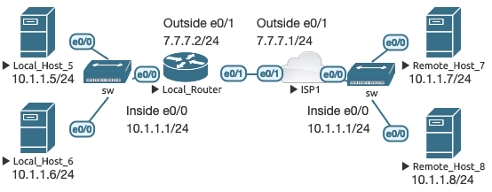
In order for devices in overlapping networks to communicate, they must believe they are talking to hosts on a different subnet. When LH5 wants to talk to RH7 at 10.1.1.7, LH5 knows that 10.1.1.7 is reachable directly on the same subnet, and sends an ARP request for 10.1.1.7’s MAC address. Since 10.1.1.7 is not actually on that network segment, it never receives the ARP request. If there was another active 10.1.1.7 host on the Local subnet, that’s the device that would receive the ARP request, not the Remote 10.1.1.7.
LR is the only device in the topology that needs to be configured for NAT. From the inside>out direction, packets with a source of 10.1.1.0/24 are translated to a source of 192.168.10.0/24. From the outside>in direction, packets with a source of 10.1.1.0/24 are translated to a source of 192.168.20.0/24.
Local_Router(config)# ip nat inside source static network 10.1.1.0 192.168.10.0 /24
Local_Router(config)# ip nat outside source static network 10.1.1.0 192.168.20.0 /24
Local_Router(config)# ip route 192.168.20.0 255.255.255.0 7.7.7.1

ISP1(config)# ip route 192.168.10.0 255.255.255.0 7.7.7.2
When a packet is sent from LH5 to RH7, LH5 knows RH7 as 192.168.20.7. When the packet leaves LH5, the source is 10.1.1.5 and the destination is 192.168.20.7. When LR receives the packet, it uses the static route to select the interface where the next hop 7.7.7.1 can be reached, and then translates the source address of the packet from LH5 to 192.168.10.5. Next, the packet undergoes another translation, with the destination IP address being translated from 192.168.20.7 to 10.1.1.7 as it is sent to the next hop 7.7.7.1 (ISP1).
When ISP1 receives the packet, it sees the source 192.168.10.5 and the destination 10.1.1.7, which it knows how to reach via its e0/0 interface. RH7 replies to the packet it sees coming from 192.168.10.5, which ISP1 knows to reach via next hop 7.7.7.2 (LR). When LR receives the return packet coming from 10.1.1.7 on the outside e0/1 interface, it translates the source to 192.168.20.7. Then the destination 192.168.10.5 is translated to 10.1.1.5, which is then routed out of the inside e0/0 interface toward the destination LH5. Simple, right? :-)
Local_Host_5# telnet 192.168.20.7 13
Trying 192.168.20.7, 13 … Open

Local_Router# debug ip nat
--LH5 request--
NAT: s=10.1.1.5->192.168.10.5, d=192.168.20.7 [5535]
NAT: s=192.168.10.5, d=192.168.20.7->10.1.1.7 [5535]
--RH7 reply--
NAT: s=10.1.1.7->192.168.20.7, d=192.168.10.5 [3425]
NAT: s=192.168.20.7, d=192.168.10.5->10.1.1.5 [3425]

Local_Router# show ip nat translations
Pro Inside global      Inside local       Outside local      Outside global
--- ---                ---                192.168.20.7       10.1.1.7
--- ---                ---                192.168.20.0       10.1.1.0
tcp 192.168.10.5:11463 10.1.1.5:11463     192.168.20.7:13    10.1.1.7:13
--- 192.168.10.5       10.1.1.5           ---                ---
--- 192.168.10.0       10.1.1.0           ---                ---
In either direction, the configured mappings trigger the NAT process twice,
once to translate the source, and once to translate the destination (hence
“twice-NAT”). This is reflected in both the debug and the output of show ip nat translations where the specific TCP entry shows four unique IP addresses.
Translating an overlapping /24 isn’t so bad, but what if you’re involved in a merger where both companies use the entire 10.0.0.0/8? This is actually probably the most common situation within enterprise network mergers. In the above example, we traded one /24 for another in both directions. Obviously, this is a little more difficult to do with an entire /8. Wouldn’t it be nice if we could use the experimental IP address range for this?
ISP1(config)# ip route 240.0.0.0 255.0.0.0 7.7.7.2
 %Invalid destination prefix
Nope, that’s not going to work. The only way this type of configuration is going to work is if you use public /8’s. This is not a big deal in a lab setting, but in the real world, you will need to determine two public /8’s that devices being translated will never need to reach directly. For example, you can view the IANA registry and determine sections of the Internet that your organization is unlikely to ever need to communicate with directly (the devices could still communicate via some kind of proxy, though). In the following example, I have randomly chosen 222/8 and 223/8.
I reconfigured LR and ISP1’s e0/0 interfaces as 10.1.1.1/8. LH5 is 10.5.5.5/8 and 10.50.50.5/8 secondary. RH7 is 10.7.7.7/8 and 10.70.70.7/8.
Local_Router# ip nat inside source static network 10.0.0.0 222.0.0.0 /8
Local_Router# ip nat outside source static network 10.0.0.0 223.0.0.0 /8
Local_Router# ip route 223.0.0.0 255.0.0.0 7.7.7.1

ISP1(config)# ip route 222.0.0.0 255.0.0.0 7.7.7.2

Local_Host_5# telnet 223.7.7.7 13
Trying 223.7.7.7, 13 … Open

Local_Router# debug ip nat
NAT: s=10.5.5.5->222.5.5.5, d=223.7.7.7 [18515]
NAT: s=222.5.5.5, d=223.7.7.7->10.7.7.7 [18515]
NAT: s=10.7.7.7->223.7.7.7, d=222.5.5.5 [20136]
NAT: s=223.7.7.7, d=222.5.5.5->10.5.5.5 [20136]

Local_Host_5# telnet 223.70.70.7 13
Trying 223.70.70.7, 13 … Open

Local_Router# debug ip nat
NAT: s=10.5.5.5->222.5.5.5, d=223.70.70.7 [5983]
NAT: s=222.5.5.5, d=223.70.70.7->10.70.70.7 [5983]
NAT: s=10.70.70.7->223.70.70.7, d=222.5.5.5 [34524]
NAT: s=223.70.70.7, d=222.5.5.5->10.5.5.5 [34524]

Local_Router# show ip nat translations
Pro Inside global      Inside local       Outside local      Outside global
--- ---                ---                223.7.7.7          10.7.7.7
--- ---                ---                223.70.70.7        10.70.70.7
--- ---                ---                223.0.0.0          10.0.0.0
tcp 222.5.5.5:17506    10.5.5.5:17506     223.70.70.7:13     10.70.70.7:13
tcp 222.5.5.5:22451    10.5.5.5:22451     223.7.7.7:13       10.7.7.7:13
--- 222.5.5.5          10.5.5.5           ---                ---
--- 222.0.0.0          10.0.0.0           ---                ---
Local knows Remote as 223/0 and Remote knows Local as 222/0. Although you lose reachability to two different public /8’s, translating the entire 10/8 network is actually somewhat easy because you only need to change the first octet in the destination address from 10 to 222 or 223 in this example. Using DNS-based lookups, it should be trivial on each side to do the name translation.
Case 13: Multi-egress for specific destinations (traffic engineering & conditional NAT)
This is the topology for the next few sections:
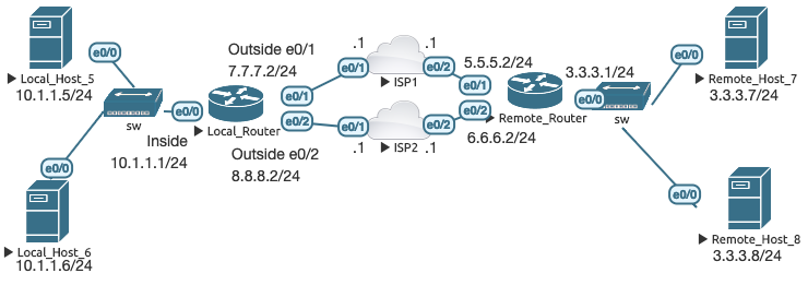
There are a couple of different ways to configure NAT when trying to reach specific destinations with multiple points of egress. One method is by extended ACL. LR is configured so that if any traffic from 10.1.1.0/24 tries to reach RH7, the link to ISP1 is used. If the same traffic is trying to reach RH8, the link to ISP2 is used instead.
Local_Router(config)# ip route 0.0.0.0 0.0.0.0 7.7.7.1
Local_Router(config)# ip route 0.0.0.0 0.0.0.0 8.8.8.1
Local_Router(config)# access-list 101 permit ip 10.1.1.0 0.0.0.255 host 3.3.3.7
Local_Router(config)# access-list 102 permit ip 10.1.1.0 0.0.0.255 host 3.3.3.8
Local_Router(config)# ip nat inside source list 101 int e0/1
Local_Router(config)# ip nat inside source list 102 int e0/2

Local_Host_5# telnet 3.3.3.7 13
Trying 3.3.3.7, 13 … Open

Local_Host_5# telnet 3.3.3.8 13
Trying 3.3.3.8, 13 … Open

Local_Router# show ip nat translations
Pro Inside global      Inside local       Outside local      Outside global
tcp 7.7.7.2:28932      10.1.1.5:28932     3.3.3.7:13         3.3.3.7:13
tcp 8.8.8.2:34422      10.1.1.5:34422     3.3.3.8:13         3.3.3.8:13

Local_Host_5# traceroute 3.3.3.7
  1 10.1.1.1 1008 msec 1 msec 0 msec
  2 7.7.7.1 1 msec 1 msec 0 msec
  3 5.5.5.2 1 msec 1 msec 1 msec
  4 3.3.3.7 1 msec *  2 msec

Local_Host_5# traceroute 3.3.3.8
  1 10.1.1.1 1 msec 0 msec 0 msec
  2 8.8.8.1 1 msec 0 msec 0 msec
  3 6.6.6.2 1 msec 0 msec 1 msec
  4 3.3.3.8 1 msec *  2 msec
As you can see, this works and the traffic is routed as was desired. When using the combination of IL defined by ACL and IG defined by exit interface, only fully-extended NAT mappings are established. What if we use NAT pools to define the IG address?
Local_Router(config)# ip nat pool ISP1 7.7.7.50 7.7.7.51 prefix-length 24
Local_Router(config)# ip nat pool ISP2 8.8.8.50 8.8.8.51 prefix-length 24
Local_Router(config)# ip nat inside source list 101 pool ISP1
Local_Router(config)# ip nat inside source list 102 pool ISP2
From LH5, I changed the IP address and connected to port 13 on RH7 and RH8 using the following combinations:
10.1.1.50 > 3.3.3.7
10.1.1.51 > 3.3.3.7
10.1.1.52 > 3.3.3.7
10.1.1.53 > 3.3.3.8
10.1.1.54 > 3.3.3.8
10.1.1.55 > 3.3.3.8
Here are the translation results:
Local_Router# show   ip nat translations
Pro Inside global      Inside local       Outside local      Outside global
tcp 7.7.7.50:11983     10.1.1.50:11983    3.3.3.7:13         3.3.3.7:13
--- 7.7.7.50           10.1.1.50          ---                ---
tcp 7.7.7.51:16054     10.1.1.51:16054    3.3.3.7:13         3.3.3.7:13
--- 7.7.7.51           10.1.1.51          ---                ---
tcp 8.8.8.50:63010     10.1.1.53:63010    3.3.3.8:13         3.3.3.8:13
--- 8.8.8.50           10.1.1.53          ---                ---
tcp 8.8.8.51:47987     10.1.1.54:47987    3.3.3.8:13         3.3.3.8:13
--- 8.8.8.51           10.1.1.54          ---                ---
While the previous approach generated only fully-extended mappings, using a NAT
pool creates simple 1:1 entries as well. I could connect successfully from
10.1.1.50 and .51, but not .52. Likewise, I was successful from 10.1.1.53 and
.54, but not .55. This is because in both cases, the pools became exhausted due
to the simple 1:1 mappings. You can get around this issue by using the
overload keyword at the end of the NAT statements. In doing so, only fully-
extended entries are created:
Local_Router# show   ip nat translations
Pro Inside global      Inside local       Outside local      Outside global
tcp 7.7.7.51:56505     10.1.1.50:56505    3.3.3.7:13         3.3.3.7:13
tcp 7.7.7.51:63255     10.1.1.51:63255    3.3.3.7:13         3.3.3.7:13
tcp 7.7.7.51:34179     10.1.1.52:34179    3.3.3.7:13         3.3.3.7:13
tcp 8.8.8.50:27964     10.1.1.53:27964    3.3.3.8:13         3.3.3.8:13
tcp 8.8.8.50:29194     10.1.1.54:29194    3.3.3.8:13         3.3.3.8:13
tcp 8.8.8.50:24644     10.1.1.55:24644    3.3.3.8:13         3.3.3.8:13
When the source is a route-map, only fully-extended NAT entries are created:
Local_Router(config)# route-map RM_ISP1
Local_Router(config-route-map)# match ip address 101
Local_Router(config)# route-map RM_ISP2
Local_Router(config-route-map)# match ip address 102
Local_Router(config)# ip nat inside source route-map RM_ISP1 pool ISP1
Local_Router(config)# ip nat inside source route-map RM_ISP2 pool ISP2

Local_Router# show ip nat translations
Pro Inside global      Inside local       Outside local      Outside global
tcp 7.7.7.51:48970     10.1.1.50:48970    3.3.3.7:13         3.3.3.7:13
tcp 7.7.7.50:58983     10.1.1.51:58983    3.3.3.7:13         3.3.3.7:13
tcp 8.8.8.50:31161     10.1.1.53:31161    3.3.3.8:13         3.3.3.8:13
tcp 8.8.8.51:47355     10.1.1.54:47355    3.3.3.8:13         3.3.3.8:13
In this case, even though the translations are fully-extended and there are no
simple 1:1 mappings, the pool is now considered exhausted and no new
connections can be made. Once again, you get around this with the overload
keyword at the end of the NAT statement. Likewise, you can achieve simple 1:1
mappings while preventing pool exhaustion when using route-maps by using the
reversible keyword in addition to overload.
Local_Router(config)# ip nat inside source route-map RM_ISP1 pool ISP1 overload reversible

Local_Router# show ip nat translations
Pro Inside global      Inside local       Outside local      Outside global
tcp 7.7.7.51:23        10.1.1.50:23       3.3.3.7:56660      3.3.3.7:56660
tcp 7.7.7.51:15226     10.1.1.50:15226    3.3.3.7:13         3.3.3.7:13
tcp 7.7.7.51:27278     10.1.1.51:27278    3.3.3.7:13         3.3.3.7:13
tcp 7.7.7.51:23201     10.1.1.52:23201    3.3.3.7:13         3.3.3.7:13
tcp 7.7.7.51:0         10.1.1.50:0        ---                ---
The middle three entries are me connecting to RH7 from 10.1.1.50, .51, and .52, all of which worked. When I did that, the first connection caused a simple 1:1 mapping of IL address 10.1.1.50 to IG pool address 7.7.7.51. The top entry shows me connecting from RH7 to 7.7.7.51 which was translated to 10.1.1.50 on the outside > in.
Finally, you can use route-maps with static mappings to enable conditional NAT.
NAT configurations become conditional by placing the route-map keyword at the
end of the statement. With the following configuration, if RH5 connects to
3.3.3.7 it will use the link to ISP1. If RH5 connects to 3.3.3.8, it will use
ISP2:
Local_Router(config)# access-list 101 permit ip 10.1.1.0 0.0.0.255 host 3.3.3.7
Local_Router(config)# access-list 102 permit ip 10.1.1.0 0.0.0.255 host 3.3.3.8
Local_Router(config)# route-map RM_ISP1
Local_Router(config-route-map)# match ip address 101
Local_Router(config# route-map RM_ISP2
Local_Router(config-route-map)# match ip address 102
Local_Router(config)# ip nat inside source static 10.1.1.5 7.7.7.50 route-map RM_ISP1
Local_Router(config)# ip nat inside source static 10.1.1.5 8.8.8.50 route-map RM_ISP2

Local_Host_5# telnet 3.3.3.7 13
Trying 3.3.3.7, 13 … Open

Local_Host_5# telnet 3.3.3.8 13
Trying 3.3.3.8, 13 … Open

Local_Host_5# telnet 3.3.3.70 13
Trying 3.3.3.70, 13 …
% Connection timed out; remote host not responding

Local_Router# show ip nat translations
Pro Inside global      Inside local       Outside local      Outside global
tcp 7.7.7.50:11701     10.1.1.5:11701     3.3.3.7:13         3.3.3.7:13
tcp 8.8.8.50:30881     10.1.1.5:30881     3.3.3.8:13         3.3.3.8:13
--- 7.7.7.50           10.1.1.5           ---                ---
--- 8.8.8.50           10.1.1.5           ---                ---
10.1.1.5 to 3.3.3.7 maps to 7.7.7.50 and 10.1.1.5 to 3.3.3.8 maps to 8.8.8.50. The connection attempt from 10.1.1.5 to 3.3.3.70 fails because it doesn’t match any of the conditional NAT statements and therefore the fully-extended mapping is not created. However, the simple NAT mappings are still present, which means if you connect to either 7.7.7.50 or 8.8.8.50 from the outside, a fully- extended mapping will be created and return traffic to those specific ports are translated:
Remote_Host_7(config-if)# ip address 3.3.3.70 255.255.255.0
Remote_Host_7# telnet 7.7.7.50 13
Trying 7.7.7.50, 13 … Open

Local_Router# show ip nat translations
Pro Inside global      Inside local       Outside local      Outside global
tcp 7.7.7.50:13        10.1.1.5:13        3.3.3.70:12959     3.3.3.70:12959
--- 7.7.7.50           10.1.1.5           ---                ---
--- 8.8.8.50           10.1.1.5           ---                ---
In Case 13, there doesn’t appear to be any functional difference between using a route-map that references an ACL versus just referencing the ACL directly in the NAT statement. However, using a route-map will open additional options such as specifying the IP next-hop or using multiple clauses to reference multiple ACLs for different behaviors.
Case 14: Multi-egress for all destinations (redundant connectivity)
Using the same topology introduced in Case 13, this case is used for redundant Internet connectivity where IL addresses are translated to overloaded IG addresses based on the exit interface. Here’s the configuration on LR:
Local_Router(config)# ip route 0.0.0.0 0.0.0.0 7.7.7.1
Local_Router(config)# ip route 0.0.0.0 0.0.0.0 8.8.8.1
Local_Router(config)# route-map RM_ISP1
Local_Router(config-route-map)# match int e0/1
Local_Router(config)# route-map RM_ISP2
Local_Router(config-route-map)# match int e0/2
Local_Router(config)# ip nat inside source route-map RM_ISP1 int e0/1 overload
Local_Router(config)# ip nat inside source route-map RM_ISP2 int e0/2 overload
I then pinged different IP addresses on the 3.3.3.0/24 subnet from LH5. Looking at the NAT translation table, it appears the egress interface is chosen at random:
Local_Router# show   ip nat translations
Pro Inside global      Inside local       Outside local      Outside global
icmp 7.7.7.2:0         10.1.1.5:0         3.3.3.7:0          3.3.3.7:0
icmp 8.8.8.2:1         10.1.1.5:1         3.3.3.8:1          3.3.3.8:1
icmp 8.8.8.2:2         10.1.1.5:2         3.3.3.71:2         3.3.3.71:2
icmp 7.7.7.2:3         10.1.1.5:3         3.3.3.72:3         3.3.3.72:3
icmp 7.7.7.2:4         10.1.1.5:4         3.3.3.81:4         3.3.3.81:4
icmp 7.7.7.2:5         10.1.1.5:5         3.3.3.82:5         3.3.3.82:5
You can see that with this configuration the router performs a crude (non- deterministic) load distribution of outbound sessions. With the dual default static routes performing ECMP, all outbound traffic is subject to translation since the configured route-maps match only on the selected outbound interface. You can change this to an active/standby configuration by simply changing the administrative distance of one of the static routes so that ECMP is no longer performed:
Local_Router(config)# ip route 0.0.0.0 0.0.0.0 7.7.7.1 20
Local_Router# clear ip nat translation *
--pings from LH5--
Local_Router# show ip nat translations
Pro Inside global      Inside local       Outside local      Outside global
icmp 8.8.8.2:6         10.1.1.5:6         3.3.3.7:6          3.3.3.7:6
icmp 8.8.8.2:7         10.1.1.5:7         3.3.3.8:7          3.3.3.8:7
icmp 8.8.8.2:8         10.1.1.5:8         3.3.3.71:8         3.3.3.71:8
icmp 8.8.8.2:9         10.1.1.5:9         3.3.3.72:9         3.3.3.72:9
icmp 8.8.8.2:10        10.1.1.5:10        3.3.3.81:10        3.3.3.81:10
icmp 8.8.8.2:11        10.1.1.5:11        3.3.3.82:11        3.3.3.82:11
Clearing the NAT translation table and performing the pings again, all traffic exits to 8.8.8.1 due to 7.7.7.1 now being less preferred. If the route to 8.8.8.1 becomes unavailable, 7.7.7.1 takes over. You can combine this with IP SLA and object tracking for reliable static routing with NAT.
With the current route-map configuration simply matching the outbound interface, all outbound traffic is subject to translation if the route-map is matched. You could instead match specific source IP addresses with a standard ACL, or specific traffic flows with an extended ACL. Likewise, you can stack multiple route-map clauses into a single route-map which are then processed top- down. The first match is selected and the traffic matching that clause is subject to translation. This method lets you build more elaborate translations within the context of a route-map instead of having to build many individual NAT statements to accomplish the same thing.
Case 15: Multi-ingress
Using the topology introduced in Case 13, the simplest method of creating a 1:1 mapping is just like Case 1, but with multiple NAT statements. In the following example, RH5’s IL address 10.1.1.5 is reachable from the outside via both 7.7.7.50 and 8.8.8.50. This creates permanent 1:1 static mappings, and when I try to connect from RH7 to both IG addresses, a temporary fully-extended mapping is entered as well.
Local_Router(config)# ip nat inside source static 10.1.1.5 7.7.7.50 extendable
Local_Router(config)# ip nat inside source static 10.1.1.5 8.8.8.50 extendable

Local_Router# show ip nat translations
Pro Inside global      Inside local       Outside local      Outside global
tcp 7.7.7.50:13        10.1.1.5:13        3.3.3.7:14293      3.3.3.7:14293
tcp 8.8.8.50:13        10.1.1.5:13        3.3.3.7:30260      3.3.3.7:30260
--- 7.7.7.50           10.1.1.5           ---                ---
--- 8.8.8.50           10.1.1.5           ---                ---
As demonstrated at the end of Case 13, you can technically perform this same
function using route-maps instead of the extendable keyword, but the route-
maps only control the creation of NAT entries for traffic initiated from the
inside. In fact, for the multi-ingress use case, the route-map doesn’t even
need to actually exist for this to work!
Local_Router(config)# ip nat inside source static 10.1.1.5 7.7.7.50 route-map RM_NONE1
Local_Router(config)# ip nat inside source static 10.1.1.5 8.8.8.50 route-map RM_NONE2

Remote_Host_7# telnet 7.7.7.50 13
Trying 7.7.7.50, 13 … Open

Local_Router# show ip nat translations
Pro Inside global      Inside local       Outside local      Outside global
tcp 7.7.7.50:13        10.1.1.5:13        3.3.3.7:56411      3.3.3.7:56411
--- 7.7.7.50           10.1.1.5           ---                ---
--- 8.8.8.50           10.1.1.5           ---                ---
Both examples are functionally identical, even when referencing non-existent
route-maps. Likewise, with both options, the keyword static places the simple
NAT entries in the mapping table upon configuration. When using the different
dynamic methods, the simple NAT entries are not placed until traffic is first
generated from the inside > out. You could also configure ip nat inside source network using these same methods to perform multi-ingress NAT for an entire
subnet.
Extra 1: NAT-on-a-stick
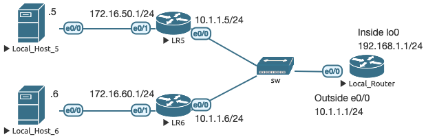
This is definitely a corner-case scenario that you might not see outside of a CCIE lab. What makes it NAT-on-a-stick is that traffic going to the NAT router is coming back out of the same interface. However, NAT on Cisco IOS requires two interfaces, so loopback 0 is configured as the NAT inside interface, and e0/ 0 is the outside.
LH5 and LH6 are routers configured as hosts (with routing disabled and the ip default-gateway set). LR5 and LR6 have a default route to 10.1.1.1. LR has two
static routes: 172.16.50.0/24 to 10.1.1.5, and 172.16.60.0/24 to 10.1.1.6. I
have also enabled service tcp-small-servers on LH5 and LH6. Before
configuring anything else, LH5 and LH6 have bidirectional reachability to each
other with the IPs defined on their e0/0 interfaces.
Policy-Based Routing (PBR) is the key to making this work by redirecting specified traffic to the lo0 interface for translation. In this first example, we want traffic coming from 172.16.50.0/24 destined to 172.16.60.0/24 to appear to actually be coming from 10.50.50.0/24.
Local_Router(config)# ip nat inside source static network 172.16.50.0 10.50.50.0 /24
Local_Router(config)# access-list 100 permit ip 172.16.50.0 0.0.0.255 172.16.60.0 0.0.0.255
Local_Router(config)# route-map RM_PBR
Local_Router(config-route-map)# match ip address 100
Local_Router(config-route-map)# set interface lo0
Local_Router(config# interface e0/0
Local_Router(config-if)# ip policy route-map RM_PBR

Local_Host_5# telnet 172.16.60.6 13
Trying 172.16.60.6, 13 … Open

Local_Router#s how ip nat translations
Pro Inside global      Inside local       Outside local      Outside global
tcp 10.50.50.5:16928   172.16.50.5:16928  172.16.60.6:13     172.16.60.6:13
--- 10.50.50.5         172.16.50.5        ---                ---
--- 10.50.50.0         172.16.50.0        ---                ---

Local_Host_6# show tcp brief
TCB       Local Address               Foreign Address             (state)
C33691A0  172.16.60.6.13             10.50.50.5.16928            TIMEWAIT
A simple 1:1 NAT mapping is created as soon as LH5 sends traffic to LH6, and the transaction completes through the extended mapping where LH5 appears to LH6 as having the source address 10.50.50.5. Since the 1:1 mapping is now established, you could connect to 10.50.50.5 from LH6 and the transaction will complete.
You can combine these techniques to perform “twice-NAT”. LH5 will believe LH6 is on the 192.168.60.0/24 network, and LH6 will continue to believe LH5 is on the 10.50.50.0/24 network:
Local_Router(config)# access-list 100 permit ip 172.16.50.0 0.0.0.255 192.168.60.0 0.0.0.255
Local_Router(config)# ip nat outside source static network 172.16.60.0 192.168.60.0 /24
Local_Router(config)# ip route 192.168.60.0 255.255.255.0 10.1.1.6

Local_Host_6# telnet 10.50.50.5 13
Trying 10.50.50.5, 13 … Open

Local_Router# debug ip nat
NAT: s=172.16.60.6->192.168.60.6, d=10.50.50.5 [46094]
NAT: s=192.168.60.6, d=10.50.50.5->172.16.50.5 [46094]

Local_Host_5# telnet 192.168.60.6 13
Trying 192.168.60.6, 13 … Open

Local_Router# debug ip nat

NAT: s=172.16.50.5->10.50.50.5, d=192.168.60.6 [14241]
NAT: s=10.50.50.5, d=192.168.60.6->172.16.60.6 [14241]

Local_Router# show ip nat translations
Pro Inside global      Inside local       Outside local      Outside global
--- ---                ---                192.168.60.6       172.16.60.6
--- ---                ---                192.168.60.0       172.16.60.0
tcp 10.50.50.5:13      172.16.50.5:13     192.168.60.6:23912 172.16.60.6:23912
tcp 10.50.50.5:43638   172.16.50.5:43638  192.168.60.6:13    172.16.60.6:13
--- 10.50.50.5         172.16.50.5        ---                ---
--- 10.50.50.0         172.16.50.0        ---                ---
In both examples, we are adding a new step to the Cisco NAT order of operations: policy routing. From the inside direction out, policy routing is performed first, followed by regular routing, then local to global translation. From the outside direction in, global to local translation occurs first, then policy routing, then regular routing.
When LH6 connects to 10.50.50.5, LR receives the packet from source 172.16.60.6 and translates it to source 192.168.60.6. The packet does not match the policy route (traffic sourced from 172.16.50.0/24 destined to 192.168.60.0/24 should be sent to interface lo0), and therefore is routed like normal. Due to the simple 1:1 mapping, the destination 10.50.50.5 is translated to 172.16.50.5 on its way to LH5.
When LH5 connects to 192.168.60.6, LR receives the packet from source 172.16.50.5 to destination 192.168.60.6 which matches the policy route and the packet is sent to interface lo0. Interface e0/0 toward 10.1.1.6 is then chosen based on the static route matching 192.168.60.0/24. As the packet moves to e0/ 0, the source is translated to 10.50.50.5 and the destination is translated to 172.16.60.6 due to the simple 1:1 mapping.
This second example could also have been configured for overlapping subnets. Likewise, the IP address chosen for lo0 on LR is essentially arbitrary, with the exception that it must not overlap with sources or destinations.
Extra 2: NAT with VRFs
Using NAT with VRFs is very similar to working with the previous use cases, just in the context of a VRF. In all previous examples, we’ve been working exclusively with the global routing table. Cisco IOS also supports NAT from a VRF to the global routing table as demonstrated in the following example:
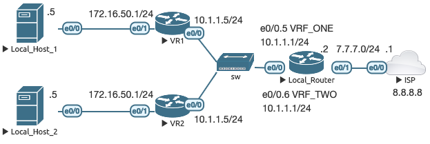
Local_Router has been reconfigured from the previous cases to have two VRFs (VRF_ONE and VRF_TWO), and the inside-facing IP address 10.1.1.1/24 on e0/0 has been placed onto both e0/0.5 and e0/0.6 in their respective VRFs. To demonstrate the concepts, all inside IP addresses have been made the same across both VRFs through VR1 and VR2, and LH1 and LH2. The ISP router contains our Internet destination 8.8.8.8 on a loopback interface. No routing is performed on ISP; it only knows about its directly connected interfaces 8.8.8.8/ 32 and 7.7.7.1/24. Here’s the initial configuration of LR:
Local_Router(config)# ip vrf VRF_ONE
Local_Router(config)# ip vrf VRF_TWO
Local_Router(config)# interface Ethernet0/0.5
Local_Router(config-if)# encapsulation dot1Q 5
Local_Router(config-if)# ip vrf forwarding VRF_ONE
Local_Router(config-if)# ip address 10.1.1.1 255.255.255.0
Local_Router(config-if)# ip nat inside
Local_Router(config)# interface Ethernet0/0.6
Local_Router(config-if)# encapsulation dot1Q 6
Local_Router(config-if)# ip vrf forwarding VRF_TWO
Local_Router(config-if)# ip address 10.1.1.1 255.255.255.0
Local_Router(config-if)# ip nat inside
Local_Router(config)# ip route vrf VRF_ONE 0.0.0.0 0.0.0.0 7.7.7.1 global
Local_Router(config)# ip route vrf VRF_ONE 172.16.50.0 255.255.255.0 10.1.1.5
Local_Router(config)# ip route vrf VRF_TWO 0.0.0.0 0.0.0.0 7.7.7.1 global
Local_Router(config)# ip route vrf VRF_TWO 172.16.50.0 255.255.255.0 10.1.1.5
Interface e0/1 is configured with ip nat outside as in previous examples and
is in the global routing table (it is not a member of any VRFs). Both VRFs are
configured with a static default route with the next hop being present in the
global routing table. Next we’ll configure a single static VRF NAT statement:
Local_Router(config)# ip nat inside source static 10.1.1.5 7.7.7.50 vrf VRF_ONE
Let’s ping 8.8.8.8 from VR1 and view the translation results:
Local_Router#show ip nat translations
Pro Inside global      Inside local       Outside local      Outside global
icmp 7.7.7.50:0        10.1.1.5:0         8.8.8.8:0          8.8.8.8:0
--- 7.7.7.50           10.1.1.5           ---                ---

Local_Router#show ip nat translations vrf VRF_ONE
Pro Inside global      Inside local       Outside local      Outside global
icmp 7.7.7.50:0        10.1.1.5:0         8.8.8.8:0          8.8.8.8:0
--- 7.7.7.50           10.1.1.5           ---                ---

Local_Router#show ip nat translations vrf VRF_TWO
Pro Inside global      Inside local       Outside local      Outside global
A simple 1:1 entry is created in the global and VRF_ONE tables, along with matching fully-extended entries for the matching ICMP session. The table for VRF_TWO is empty, as expected. If you try to ping from LH1 it will fail, because the mapping as entered is only for source 10.1.1.5 in VRF_ONE. Likewise, pinging from VR2 won’t work even though it has the source 10.1.1.5 because it is in VRF_TWO. Let’s add another mapping for VRF_TWO:
Local_Router(config)# ip nat inside source static 10.1.1.5 7.7.7.50 vrf VRF_TWO
 % similar static entry (10.1.1.5 -> 7.7.7.50) already exists
That doesn’t work. However, there is a command that will let you add multiple entries:
Local_Router(config)# ip nat inside source static 10.1.1.5 7.7.7.50 vrf VRF_ONE match-in-vrf
Local_Router(config)# ip nat inside source static 10.1.1.5 7.7.7.50 vrf VRF_TWO match-in-vrf
When you issue the above commands, IOS automatically adds the extendable
keyword to your statements. If you try the pings to 8.8.8.8 from VR1 and VR2
again, the pings do not work, even though the translation entries are created:
Local_Router# show   ip nat translations
Pro Inside global      Inside local       Outside local      Outside global
icmp 7.7.7.50:1        10.1.1.5:1         8.8.8.8:1          8.8.8.8:1
--- 7.7.7.50           10.1.1.5           ---                ---
--- 7.7.7.50           10.1.1.5           ---                ---
icmp 7.7.7.50:0        10.1.1.5:0         8.8.8.8:0          8.8.8.8:0
--- 7.7.7.50           10.1.1.5           ---                ---

Local_Router# show ip nat translations vrf VRF_ONE
Pro Inside global      Inside local       Outside local      Outside global
icmp 7.7.7.50:1        10.1.1.5:1         8.8.8.8:1          8.8.8.8:1
--- 7.7.7.50           10.1.1.5           ---                ---

Local_Router# show ip nat translations vrf VRF_TWO
Pro Inside global      Inside local       Outside local      Outside global
icmp 7.7.7.50:0        10.1.1.5:0         8.8.8.8:0          8.8.8.8:0
--- 7.7.7.50           10.1.1.5           ---                ---
I spent quite a bit of time testing and searching but I could not find a reason why it doesn’t work like this. All fully-extended entries contain the necessary information to figure out which traffic is associated with which VRF. However, I found three ways around this. The first way is to use NVI-based configuration instead (covered in section Extra 3: NVI). The second way is to use a different IG address for each VRF:
Local_Router(config)# ip nat inside source static 10.1.1.5 7.7.7.50 vrf VRF_ONE
Local_Router(config)# ip nat inside source static 10.1.1.5 7.7.7.51 vrf VRF_TWO

Local_Router# show ip nat translations
Pro Inside global      Inside local       Outside local      Outside global
icmp 7.7.7.50:4        10.1.1.5:4         8.8.8.8:4          8.8.8.8:4
--- 7.7.7.50           10.1.1.5           ---                ---
icmp 7.7.7.51:3        10.1.1.5:3         8.8.8.8:3          8.8.8.8:3
--- 7.7.7.51           10.1.1.5           ---                ---

Local_Router# show ip nat translations vrf VRF_ONE
Pro Inside global      Inside local       Outside local      Outside global
icmp 7.7.7.50:4        10.1.1.5:4         8.8.8.8:4          8.8.8.8:4
--- 7.7.7.50           10.1.1.5           ---                ---

Local_Router#show ip nat translations vrf VRF_TWO
Pro Inside global      Inside local       Outside local      Outside global
icmp 7.7.7.51:3        10.1.1.5:3         8.8.8.8:3          8.8.8.8:3
--- 7.7.7.51           10.1.1.5           ---                ---
Everything looks the same as before except using a different IG address for the VRF_TWO mapping, but with this method the pings go through. The other method is to use PAT / NAT overloading. With the following example, all inside addresses are matched to the same NAT pool-based IG address for both VRFs:
Local_Router(config)# access-list 1 permit any
Local_Router(config)# ip nat pool NP_ONE 7.7.7.50 7.7.7.50 prefix-length 24
Local_Router(config)# ip nat inside source list 1 pool NP_ONE vrf VRF_ONE overload
Local_Router(config)# ip nat inside source list 1 pool NP_ONE vrf VRF_TWO overload

Local_Router# show ip nat translations
Pro Inside global      Inside local       Outside local      Outside global
icmp 7.7.7.50:2        172.16.50.5:2      8.8.8.8:2          8.8.8.8:2
icmp 7.7.7.50:0        172.16.50.5:2      8.8.8.8:2          8.8.8.8:0

Local_Router#show ip nat translations vrf VRF_ONE
Pro Inside global      Inside local       Outside local      Outside global
icmp 7.7.7.50:2        172.16.50.5:2      8.8.8.8:2          8.8.8.8:2

Local_Router#show ip nat translations vrf VRF_TWO
Pro Inside global      Inside local       Outside local      Outside global
icmp 7.7.7.50:0        172.16.50.5:2      8.8.8.8:2          8.8.8.8:0
Pinging from LH1 and LH2 works just fine, and the translations are mapped to the proper VRFs, even though all IL and IG addresses are the same. One thing that is nice about using the NAT pool for IG addresses is that you could easily assign different ranges by using a different pool for each VRF.
What about intra-VRF NAT? To keep things simple, let’s take VRF_TWO out of the
picture for now and just work with VRF_ONE. All previous NAT statements are
removed, LR’s e0/1 interface toward ISP is placed into VRF_ONE, and the static
default route in VRF_ONE has had the global keyword removed so that all
traffic stays within VRF_ONE. Then we do a simple mapping for IL 10.1.1.5 on
VR1 to IG 7.7.7.50:
Local_Router(config)# interface Ethernet0/1
Local_Router(config-if)# ip vrf forwarding VRF_ONE
Local_Router(config-if)# ip address 7.7.7.2 255.255.255.0
Local_Router(config-if)# ip nat outside
Local_Router(config)# ip route vrf VRF_ONE 0.0.0.0 0.0.0.0 7.7.7.1
Local_Router(config)# ip nat inside source static 10.1.1.5 7.7.7.50 vrf VRF_ONE

Local_Router# show ip nat translations
Pro Inside global      Inside local       Outside local      Outside global
icmp 7.7.7.50:6        10.1.1.5:6         8.8.8.8:6          8.8.8.8:6
--- 7.7.7.50           10.1.1.5           ---                ---

Local_Router#show ip nat translations vrf VRF_ONE
Pro Inside global      Inside local       Outside local      Outside global
icmp 7.7.7.50:6        10.1.1.5:6         8.8.8.8:6          8.8.8.8:6
--- 7.7.7.50           10.1.1.5           ---                ---
Nothing special: it works exactly the same way as all the other examples but contained within the single VRF.
What about NAT between VRFs? Classic IOS can do this with NVI (inter-VRF example covered in Extra 3: NVI). IOS-XE does not support NVI at all, but can perform inter-VRF NAT (and a whole lot more) with VASI (VRF-Aware Software Infrastructure).
Extra 3: NAT Virtual Interface (NVI)
All previous examples use “domain-based” NAT, where domains are defined by designating inside and outside interfaces. With traditional domain-based NAT you must be aware of the order of operations (as I’ve hopefully drilled into you throughout this post). With NVI, routing is always done first, then translation, regardless of direction. This is due to the use of the logical interface NVI0. Per the Cisco documentation, a NAT table is maintained per-interface with NVI, but you cannot use route-maps or the NAT-on- a-stick configuration.
We’ll use the same topology as Case 1, but with the inside/outside semantics removed:
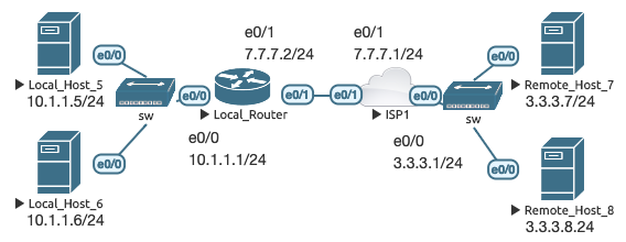
Local_Router(config)# interface e0/0
Local_Router(config-if)# ip nat enable
Local_Router(config)# interface e0/1
Local_Router(config-if)# ip nat enable
Local_Router(config)# ip nat source static 10.1.1.5 7.7.7.5

Remote_Host_7# telnet 7.7.7.5 13
Trying 7.7.7.5, 13 … Open

Local_Router# show ip nat nvi translations
Pro Source global      Source local       Destin  local      Destin  global
tcp 3.3.3.7:26177      3.3.3.7:26177      7.7.7.5:13         10.1.1.5:13
--- 7.7.7.5            10.1.1.5           ---                ---
NVI configuration is mostly the same as before, except you do not specify
inside or outside, and the translation is source-based only (there is no ip nat destination command). You can use ACLs, pools, entire networks, and VRFs,
but not route-maps.
As mentioned in the NAT with VRFs section (Extra 2), you can use NVI to perform inter-VRF NAT on Classic IOS. Using the topology from that section, we’ll configure a simple static 1:1 NAT with NVI so that VR1 can access VR2 and vice- versa, even though they have the same IP addresses and they are members of different VRFs:
On LR, interfaces e0/0.5 and e0/0.6 are configured with ip nat enable. VR1
knows VR2 as 7.7.7.52, and VR2 knows VR1 as 7.7.7.51:
Local_Router(config)# ip nat source static 10.1.1.5 7.7.7.51 vrf VRF_ONE
Local_Router(config)# ip nat source static 10.1.1.5 7.7.7.52 vrf VRF_TWO

VR1# telnet 7.7.7.52
Trying 7.7.7.52 … Open
VR2#

VR2# telnet 7.7.7.51
Trying 7.7.7.51 … Open
VR1#

Local_Router# show ip nat nvi translations
Pro Source global      Source local       Destin  local      Destin  global

Local_Router# show ip nat nvi translations vrf VRF_ONE
Pro Source global      Source local       Destin  local      Destin  global
tcp 7.7.7.51:23        10.1.1.5:23        7.7.7.52:24143     10.1.1.5:24143
tcp 7.7.7.51:18628     10.1.1.5:18628     7.7.7.52:23        10.1.1.5:23
--- 7.7.7.51           10.1.1.5           ---                ---

Local_Router# show ip nat nvi translations vrf VRF_TWO
Pro Source global      Source local       Destin  local      Destin  global
tcp 7.7.7.52:23        10.1.1.5:23        7.7.7.51:18628     10.1.1.5:18628
tcp 7.7.7.52:24143     10.1.1.5:24143     7.7.7.51:23        10.1.1.5:23
--- 7.7.7.52           10.1.1.5           ---                ---
The global NAT table is bypassed completely, and the relevant mappings remain within their respective VRFs.
NVI didn’t really take off, and in fact has been removed from IOS-XE, so it’s better to focus your attention on domain-based NAT.
Resources
Key takeaways from this post:
- From the inside > out, Cisco IOS performs routing first, then translation
- From the outside > in, Cisco IOS performs translation first, then routing
- Static NAT (whether inside or outside) uses the keyword
static - Dynamic NAT uses route-maps, ACLs, NAT pools, and/or overloading
- Conditional NAT uses route-maps at the end of the NAT configuration statement
- Source NAT changes the source IP address during translation (
ip nat inside sourceorip nat outside source) - Destination NAT changes the destination IP address during translation, and
Cisco IOS only supports inside translation (
ip nat inside destination) - NVI-based configuration is exclusively source NAT
- NAT works with VRFs including VRF-to-global, intra-VRF, and inter-VRF
- The
extendablekeyword allows you to use the same IL address in multiple configuration statements - The
no-aliaskeyword prevents the router from responding to ARP requests for the translated IP address - The
overloadkeyword is used with Port Address Translation (PAT) - The
reversiblekeyword is used with route-maps for 1:1 entries to allow traffic to be initiated from the outside - The
networkkeyword is used for 1:1 mappings for entire networks with matching hosts - The
add-routekeyword is used to add a dynamic static route for outside source translations to combat the NAT order of operations
In addition to the Cisco documentation, here are a few links from which I drew heavily upon to write this post:
- Jeff Kronlage: Everything NAT
- Daniel Dib: A look at NAT - inside, outside and NAT on a stick
- Joe Astorino: The “Inside & Outside” of NAT for Overlapping Networks
- Nick Russo: NAT44 (network4dev project)
- Jeff Doyle: Routing TCP/IP Volume II, 2nd Edition (Chapter 10)
PDF version of this article
Mind Map (CliffNotes)