MikroTik Automated MPLS L3VPN Lab
I am breaking out of the Cisco wheelhouse a little bit by using MikroTik RouterOS to build on my previous work of automating a base-level lab configuration. Working with another network operating system that uses a completely different syntax allows you to learn the various protocols in a more meaningful way (in my opinion). When you configure a single vendor’s equipment, it is easy to get in the habit of pushing out configurations without taking the time to understand the meaning behind the commands.
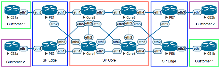
This lab demonstrates an automated configuration of a basic MPLS L3VPN service, including four SP core routers, four SP PE routers, and four CE routers representing two different customers.
The building blocks of a basic MPLS L3VPN include:
- Loopback IP addresses assigned to all SP routers.
- Reachability between the loopbacks, whether through static or dynamic routing. A flat OSPF topology was chosen for this lab.
- LDP to advertise MPLS labels between the SP routers.
- BGP sessions between PE routers to distribute the VPNv4 NLRI.
- VRFs for customers defined on the PE routers.
- Redistribution of customer routing information into BGP for transport across the SP network.
My [previous lab automation] (/posts/2018-04-26-automating-labs-now-with-yaml-and-multi-threading/) relied on telnet connections to devices using netmiko, which includes logic to handle the Cisco devices (such as entering privileged EXEC and configuration modes, etc.). With this lab, I am still using telnet since the hypervisor (EVE-NG) acts as a telnet-based terminal server, but netmiko does not currently work with MikroTik in the way that I need it to. Through trial and error, I worked out a script using Python3’s built-in telnet library.
The Python3 script and associated YAML and Jinja2 files that accompany this post are available on my GitHub page.
Let’s dissect this lab a little bit. The Python3 script is based off the work I did previously with the multi-threaded configuration. The script imports and creates structured data out of the YAML file, then processes the Jinja2 template to build complete configurations. This process is exactly the same as what I had done before. The difference this time is in how the Python3 script handles sending the completed configuration to the MikroTik devices.
Netmiko has had extensive testing and verification done for Cisco IOS behaviors, but not yet for MikroTik RouterOS. Configuration syntax aside, the general behavior of RouterOS is different from Cisco IOS as well. Upon booting an unconfigured instance of the CHR version of RouterOS, you are presented with a default login (admin / no password), and asked if you wish to view the software license agreement. My Python3 script accounts for this.
I also discovered that using this method to push configurations (where the telnet connection represents a serial console port), MikroTik does not seem to respond to the newline character ("\n"), so I had to use “\r” instead. Finally, I discovered that the MikroTik CHR had an issue rapidly accepting commands. The application of the pushed commands is inconsistent. My workaround was to introduce a one-second pause between the sending of each command. I also had to open a telnet console in advance to all devices to be configured, even though the script will be doing the same thing. For some reason, the configurations would not apply accurately and consistently unless I already had a telnet session pre-established in another window.
The other issue I had set me back a few hours worth of troubleshooting, until I finally had to ask someone for help. Using the current version of EVE-NG for the hypervisor, I was using version 6.42.3 of the CHR MikroTik RouterOS. I discovered every time I booted the routers, the interfaces were not connected as they were displayed in the lab. It was almost as if the actual interfaces were scrambled, and it seemed to be random with every boot. Fortunately, my friend Kevin Myers came to the rescue! There seems to be an unknown bug somewhere in the interactions between EVE-NG and RouterOS for versions beyond 6.39. After talking to Kevin, I tried RouterOS version 6.38.7 and that resolved the issue.
Now to the automated configuration. This is represented in the Jinja2 file.
The following configuration section applies to all routers in the lab. It sets the hostname (as defined in the YAML file), and adds a loopback interface. MikroTik treats loopback interfaces no differently than a regular bridged Layer 3 interface (similar to an SVI or a BVI on Cisco equipment). I named the interface “lo1” out of convention, but the name is arbitrary and can be anything.
/system identity set name {{ host }}
/interface bridge add name=lo1
Go through all interfaces defined for all devices, and assign the IP addresses. Add the appropriate LDP configuration if the interface is to be enabled for LDP.
{%- for iface in interfaces %}
/ip address add address={{ iface[1] }}/{{ iface[2] }} interface={{ iface[0] }}
{% if iface[3] %}
/mpls ldp interface add interface={{ iface[0] }}
{%- endif %}
{%- endfor %}
This lab uses eBGP as the PE-CE routing protocol. If the device is a CE router (as indicated by having “CE” in its hostname), enable BGP for the defined ASN, redistribute connected routes, and add the PE BGP peer.
{%- if 'CE' in host %}
/routing bgp instance set default as={{ bgp_asn }} redistribute-connected=yes
{%- for peer in bgp_peers %}
/routing bgp peer add remote-address={{ peer[1] }} remote-as={{ peer[0] }}
{%- endfor %}
{%- endif %}
If the router belongs to the service provider (whether Core or PE), enable OSPF and define the router-id. Since I kept all interfaces in the global routing table within the 10.0.0.0/8 network, I added the blanket statement to enable those interfaces in OSPF area 0. This could be easily modified for variables in the YAML file if necessary. I did not do that here in the interest of keeping things simple. Next, LDP is enabled with the same IP address as defined on the loopback interface.
{%- if 'Core' in host or 'PE' in host %}
/routing ospf instance set 0 router-id={{ router_id }}
/routing ospf network add network=10.0.0.0/8 area=backbone
/mpls ldp set enabled=yes transport-address={{ router_id }}
{%- endif %}
Finally, the remaining configuration applies only to the PE routers to enable the MPLS L3VPN service.
This enables BGP globally and defines the local ASN:
{%- if 'PE' in host %}
/routing bgp instance set default as={{ bgp_asn }}
This configuration set goes through all defined VRFs for each PE. In the interest of keeping things simple, only a single VRF is defined on each PE, though more VRFs can be defined by simply adding the information in the YAML file. The first configuration line (denoted by “/”) names the VRF, which interfaces will participate, the Route Distinguisher, and the import and export Route Targets. The second line creates a BGP instance for the particular VRF and associates it to the VRF. The third line enables redistribution of IPv4 routes from the BGP VRF RIB to global BGP VPNv4 routes to be sent to the other PE routers.
{%- for vrf in vrfs %}
/ip route vrf add routing-mark={{ vrf[0] }} interfaces={{ vrf[1] }} \
 route-distinguisher={{ vrf[2] }} export-route-targets={{ vrf[3] }} \
 import-route-targets={{ vrf[4] }}
/routing bgp instance add name={{ vrf[0] }} router-id={{ router_id }} \
 as={{ bgp_asn }} routing-table={{ vrf[0] }}
/routing bgp instance vrf add instance=default routing-mark={{ vrf[0] }} \
 redistribute-connected=yes redistribute-other-bgp=yes
{%- endfor %}
This final configuration section defines the PE BGP peers. The configuration is separated into two parts: is the peer part of a VRF or not? If the peer is part of a VRF, regular IPv4 BGP NLRI is exchanged. If the peer is not part of a VRF, we are only interested in exchanging VPNv4 NLRI.
{%- for peer in bgp_peers %}
{%- if peer[2] %}
/routing bgp peer add instance={{ peer[2] }} remote-address={{ peer[1] }} \
 remote-as={{ peer[0] }}
{%- endif %}
{%- if not peer[2] %}
/routing bgp peer add remote-address={{ peer[1] }} remote-as={{ peer[0] }} \
 address-families=vpnv4 update-source=lo1
{%- endif %}
{%- endfor %}
{%- endif %}
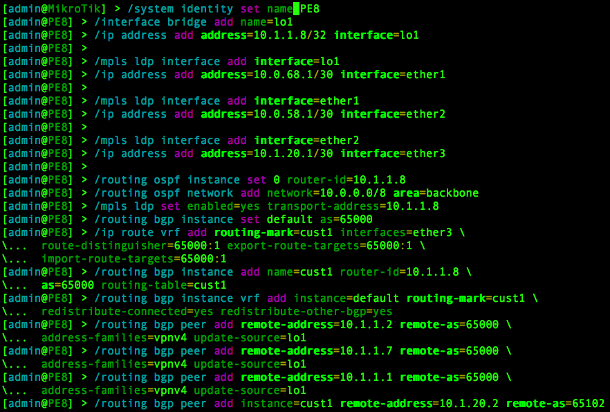
Assuming all variables are correctly defined in the YAML file, running the Python3 script should produce successful results for a baseline configuration. Here is an example of the output on PE8:
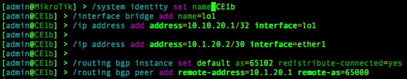
This is the output of the corresponding CE router (CE1b):
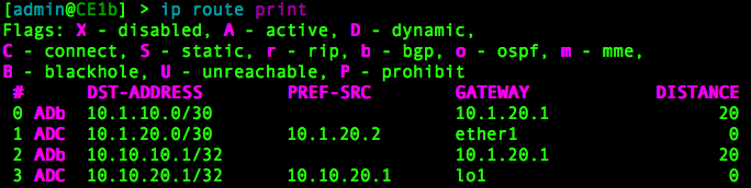
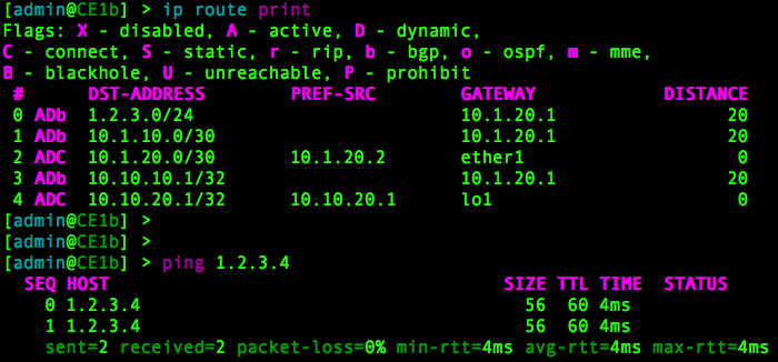
On all routers, you can verify the IP routing table with:
/ip route print
This shows the current base-level routing table from CE1b. It has reachability to the routes in CE1a:
If we go to CE1a and create a new bridged interface, it will appear in the routing table of CE1b after an IP address is assigned to it. This is because our baseline configuration automatically redistributes connected interfaces.

Verified from CE1b:
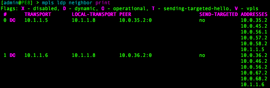
On the PE routers, you can verify the LDP neighbors with:
/mpls ldp neighbor print
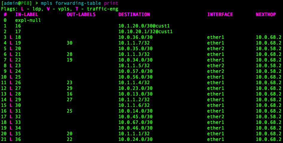
Verify the MPLS FIB with:
/mpls forwarding-table print
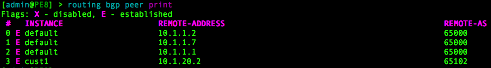
Verify BGP peers:
/routing bgp peer print
This lab keeps things simple to demonstrate the concepts. More advanced configurations such as the ability to have the same BGP ASN present at multiple customer sites, dual-homed CE routers, BGP route reflectors, and more complex route-target import/export scenarios are not demonstrated in this lab. However, I have shown how you can easily deploy a base configuration for which you can then dive into more advanced scenarios.
If you’re building an MPLS L3VPN, you’re always going to need the building blocks in place. By automating the base-level configuration, you save yourself from the monotony of typing the same commands over and over again before you can get to the more interesting stuff. As always, make sure you understand what you are automating before you do it, otherwise you will waste valuable time when you need to troubleshoot when things go wrong.