Easy Disaster Recovery Plan
DR plans encompass everything from no plan whatsoever (failing to plan is planning to fail), to active/active workloads distributed among several geo- redundant datacenters. This spectrum, just like nearly everything else in business, goes from zero to enormous cost and complexity. In the interest of keeping things simple, I designed a relatively inexpensive and uncomplicated enterprise DR plan that can be adapted and scaled with organizational requirements.
The initial design starts with two datacenters (or campuses, or a couple boxes in a rented colo cage, whatever your situation may be). One is primary (Datacenter A), and the other functions as a cold standby with some secondary production traffic (Datacenter B). In this example, I am using a single router, and a single VRF-capable Layer 3 switch in Datacenter B.
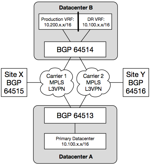
With this design, Datacenter A serves Site X and Site Y for normal production traffic. Datacenter B also serves normal production traffic, but mostly for secondary systems for when individual primary systems at Datacenter A become available, which is different from a full disaster recovery scenario. This demonstrates the cost savings of starting out with partial redundancy. Services that are deemed critical to infrastructure (such as DNS) have live systems simultaneously active in both datacenters. However, it is not a full replacement for all systems should Datacenter A become completely unavailable.
The Layer 3 switch in Datacenter B is divided into two VRFs: one for secondary production traffic, and one for disaster recovery traffic which mirrors the prefixes available in the primary datacenter. The DR VRF is always active, and can be prepared and maintained using whatever resources are required before an actual DR event occurs.
During normal production, the router at Datacenter B (indicated in the diagram as BGP 64514) sees both the production 10.100.x.x/16 and DR 10.100.x.x/16 networks. When a router receives multiple routes from different protocols, it needs to decide which route to believe. This router is configured to install the production 10.100.x.x/16 routes from Datacenter A in its FIB as long as it is receiving them from BGP. If those routes disappear, the DR 10.100.x.x/16 routes are installed, instead.
This means the DR 10.100.x.x/16 routes will be inaccessible from the rest of the network during normal production. With this design using a Layer 3 switch and VRFs, the SVIs are assigned to either the production or DR VRF. You can access the DR routes during normal production by configuring a jump host that contains at least two network interfaces: one in the production VRF, and one in the DR VRF.
Finally, a disaster recovery plan is incomplete if you do not test it. On the BGP router in Datacenter B, you can set up filtering to prevent the production 10.100.x.x/16 routes from being learned by BGP. This will cause the Datacenter B router to believe the DR 10.100.x.x/16 routes are the “real” routes. Likewise, for DR testing purposes, you should ensure that the Datacenter B BGP router does not advertise the 10.100.x.x/16 routes back to the rest of the network. You would only do that during an actual DR event. With the bidirectional filtering in place, you can use one or more hosts on the secondary production 10.200.x.x/16 network to test the validity of the recovery. After the results of the test are verified, you can remove the inbound BGP filtering to restore Datacenter B to normal production.
During a DR test, hosts in other parts of the network (such as Site X and Site Y) can still access hosts in the 10.200.x.x/16 network, and they will still use the 10.100.x.x/16 routes present in Datacenter A. Hosts in Datacenter A can reach hosts on the 10.200.x.x/16 network, but the replies will be sent to the DR VRF. You can use static routes on the Datacenter B BGP router to override this behavior. For example, if during DR testing a system in the DR environment absolutely must reach another system in the production network in Datacenter A, a static /32 route can be entered into the Datacenter B router pointing toward the MPLS L3VPN.
This design starts small and simple, which is sometimes all you need to reach the particular business goals. It also represents an older way to do things by using an active/standby model, based on systems that are not prepared to have their IP addresses changed. The tradeoff is a much lower cost since additional hardware and software licensing are not required until an actual disaster (depending on what is being recovered).
A more modern (albeit more expensive) model is active/active using different subnets and load-balancers. The client-facing IP prefixes could be advertised from both datacenters, fronted by the load-balancers. The clients would reach their closest load-balancer (anycast style), and the load-balancer would redirect to the proper server to complete the connection (depending on the application architecture, of course). This is more expensive because it requires a duplication of hardware and software (including licensing) to maintain the active/active environment.
The tradeoff is a much quicker recovery time. In fact, the users might not even be aware of an outage if proper planning and testing is performed. It all depends on the business weighing the risks versus the costs. Some businesses can tolerate the active/standby model, many cannot.