Easy Cisco VPLS L2VPN Automated Lab
In this lab, I cover automating the setup for a simple 3-customer VPLS L2VPN. I detail the basic configuration components, as well as automating the deployment to alleviate repetitive configuration commands. Like many technologies, it is best to start simple to build a foundation of knowledge before moving on to a more advanced depth. This lab is meant to be an introduction to multipoint L2VPN using MPLS, and more advanced options are not covered in this post. The automation and topology are based on my previous posts.
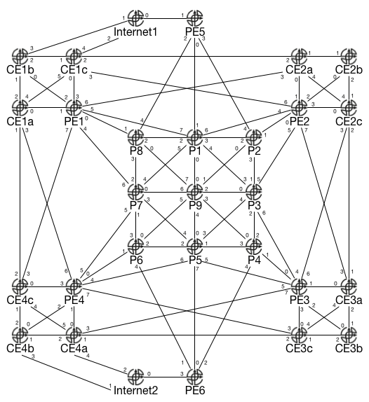
The physical topology is the same as before, though various interface names have changed (the above is only a reference of the topological layout, not of the actual interfaces). The lab relies on three files available on my GitHub page: the Python3 script, Jinja2 template, and YAML description file.
VPLS is a collection of interconnected pseudowires. Pseudowires act as virtual point-to-point connections through the carrier network. Cisco uses Virtual Forwarding Instances and Bridge Domain software constructs to emulate a multipoint LAN (like a traditional switch). Other vendors use equivalent constructs with potentially different names. By default, split horizon bridging is also used, so that frames entering a particular interface are not sent back out that same interface, which helps prevent Layer 2 loops.
The underlying infrastructure used by VPLS begins similarly to MPLS L3VPNs: to avoid manual configurations, you need an underlying IGP to provide reachability to the loopback interfaces of all the P and PE routers, and LDP to automatically generate and advertise labels. Pseudowires in an MPLS network rely on targeted LDP sessions between the PE routers. I chose IS-IS as the lab IGP with all routers configured for the same area in Level-2.
The next step is to configure pseudowires between the PE routers. This lab uses manual configuration to keep things simple and easy to understand. There are more advanced options such as BGP-based autodiscovery which negates much of the manual configuration on the PE routers. This lab does not run BGP at all. Each PE router must have a full mesh of pseudowires configured between all PE routers where the customer has an attachment circuit. This lab features four PE routers (PE1 - PE4) with three individual customers attached to each (CEa - CEc).
Each pseudowire is configured for MPLS encapsulation, frame sequencing, and LDP as the signaling protocol. For BGP-based autodiscovery, each pseudowire also needs the control-word option enabled, but that optional here. Cisco IOS allows us to put these common settings into a template configuration:
template type pseudowire PWTEMP
 encapsulation mpls
 sequencing both
 control-word include
 signaling protocol ldp
Next, a manual pseudowire must be created for each PE to PE connection for all participating nodes. This lab has four PEs with three customers attached to each, which requires nine PWs configured on each router (PEs minus one multiplied by customers). Since this lab is small (and automated), this is not a big deal, but you can see how quickly something like BGP autodiscovery can be extremely beneficial.
The basic syntax is:
interface pseudowire NUM
 description X
 source template type pseudowire PWTEMP
 neighbor IP NUM
For example, the lab configuration on PE1 for the pseudowire between PE1 and PE2 for customer number 1 could be:
interface pseudowire 112
 description SI10 PE1-PE2
 source template type pseudowire PWTEMP
 neighbor 10.255.1.2 112
The encapsulation and LDP signaling are automatically populated into the configuration from the template. The NUM (112 in this example) does not have to match, but it makes for easier readability and troubleshooting. I used 112 to refer to customer 1, connection between PE1 and PE2. This scheme is probably infeasible for larger environments. In the optional description, I reference SI10, Service Instance 10. Part of the overall VPLS configuration is defining a Service Instance (covered shortly), which I chose to use 10, 20, and 30 for customer 1, 2, and 3 respectively. As mentioned, you must configure a separate PW for each customer between all participating PEs. A full mesh is typically desired, but you can also create a customer hub-and-spoke (or partial mesh) network by configuring PWs between specific PEs and not necessarily all of them.
After the PWs are defined, the Virtual Forwarding Instance must be instantiated. The basic syntax is:
l2vpn vfi context NAME
 vpn id NUM
 l2protocol forward
 member pseudowire X
 member pseudowire Y
For example:
l2vpn vfi context Customer1
 vpn id 10
 l2protocol forward
 member pseudowire112
 member pseudowire113
 member pseudowire114
The VPN ID is essentially arbitrary for this configuration, and I made it match
the service instance for readability. The l2protocol forward command enables
Layer 2 control frames (such as CDP and STP, among others) to cross the VPLS.
This is configured per-VFI context, and per-AC (attachment circuit) interface
as well.
Next, a Bridge Domain is defined. The BD binds together the VFI and the AC interfaces on the PE router:
bridge-domain NUM
 member AC service-instance NUM
 member vfi NAME
Customer 1 example:
bridge-domain 10
 member Gi2 service-instance 10
 member vfi Customer1
Once again, the bridge-domain value does not need to match the service-instance value, but it makes it easier to read. By specifying multiple members, you can have multiple AC interfaces and even multiple VFI members as part of the bridge domain on the PE router, though that defeats the purpose of customer separation.
Finally, the AC is configured:
interface INT
 service instance NUM ethernet
  encapsulation default
  l2protocol forward
PE1 Customer 1 example:
interface Gi2
 service instance 10 ethernet
  encapsulation default
  l2protocol forward
As mentioned, the l2protocol forward option must be enabled both on the VFI
and the AC. If it is not enabled at the VFI level, Layer 2 control frames will
not be forwarded. If it is not enabled on the AC, just that particular AC is
affected. This could be useful in a hub-and-spoke scenario if, for example, you
only wanted to see CDP or LLDP frames coming from the spokes toward the hub,
but not from the hub toward the spokes.
The service instance construct is very powerful, and is part of the Ethernet Virtual Circuit functionality. For example, you can have multiple SIs present on a single Ethernet link to provide logically separated services. You could connect a switch to the AC and have multiple customers connected to the single physical interface on the PE router, but still have logical separation through VLANs on the switch.
The encapsulation method is what enables this functionality. Cisco refers to
the default encapsulation as the “catch all” method. This means it will
forward both tagged and untagged frames across the VPLS. You can specify
untagged, where any frame with a tag is rejected. With the dot1q
encapsulation, you can specify that a certain tag MUST be present, or you can
specify that the frame must contain ANY tag (but it drops the frame if it is
untagged, which requires tagging the native VLAN on the customer side). You can
also get into much more complicated scenarios involving S-tags and C-tags with
different kinds of rewrite options where the tag values can be changed during
transit.
With all of the components of the VPLS configured (PWs, VFI, BD, ACs), we can perform some verifications.
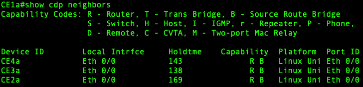
From one of the CE routers, show cdp neighbors reveals that the CE routers
believe they are all connected directly to each other, and to only those
routers within their customer VPLS instance:
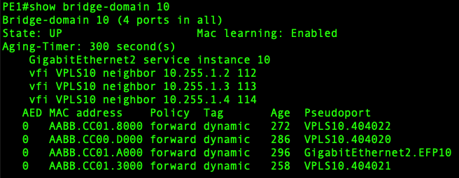
On the PE router, show bridge-domain reveals the participating interfaces and
learned MAC addresses:
There are a few other commands that display overlapping information, such
as show l2vpn atom vc which displays the PW interfaces and which targeted LDP
neighbors they are matched to along with their status. The show mpls
l2transport vc command displays similar information. One of the more
interesting verifications is show mpls l2transport pwid which reveals the
MPLS labels used for each PW.
This post offered an introductory look into configuring basic VPLS on Cisco IOS. VPLS makes the service provider network appear as a single virtual switch to the customer edge devices. By performing manual configuration as a first step, you can see how VPLS is actually just a collection of point-to-point pseudowires, and how there is an opportunity to configure different topologies and connectivity options depending on both the service provider and customer’s needs. This post did not go into more advanced topics such as BGP autodiscovery, or securing the service provider network by introducing limits, such as the number of MAC addresses can be contained in a particular VPLS instance.